Oscillating motor

a technology of oscillating motor and piston engine, which is applied in the direction of fluid-pressure actuator, sealing arrangement of engine, rotary or oscillating piston engine, etc., and can solve the problem of comparatively long bore to be produced

Inactive Publication Date: 2005-04-19
ZF SACHS AG
View PDF11 Cites 12 Cited by
  • Summary
  • Abstract
  • Description
  • Claims
  • Application Information

AI Technical Summary

Benefits of technology

[0007]The object of the invention is to provide means for equalizing the pressure between the ring-shaped spaces for the seals in such a way that the longitudinal force acting between the motor shaft and the cylinder is minimized.
[0009]The essential advantage is that the pressure equalization channel can be produced much more easily.
[0010]When, for example, the pressure equalization channel is machined into the motor shaft, said pressure equalization channel can be produced very quickly and accurately by a simple milling tool. As an alternative, the pressure equalization channel can be provided in the sleeve. The pressure equalization channel can be produced by a simple groove-clearing operation.
[0011]In another advantageous embodiment, the pressure equalization channel has a connection to a working chamber. The advantage of this measure is not only that the pressure levels between the two ring-shaped spaces of the sealing arrangements can be equalized, but also that the pressure can escape into a working space with a much lower pressure level.
[0014]For the production of a motor shaft, it is generally of interest with respect to simplicity and low production costs for the sleeve to carry the vanes for the motor shaft, because then the sleeve and the vanes can both be produced from a single extruded section, which at least minimizes the need for complicated finishing steps.

Problems solved by technology

A general problem with pressure-preloaded seals arranged in pairs in an oscillating motor is that the pressure levels at the two seals are different, which means that a longitudinal force is created, which tries to shift the motor shaft with respect to the cylinder.
The problem, however, is that a comparatively long bore must be produced.

Method used


Image

  • Oscillating motor
  • Oscillating motor
  • Oscillating motor

Examples


Embodiment Construction

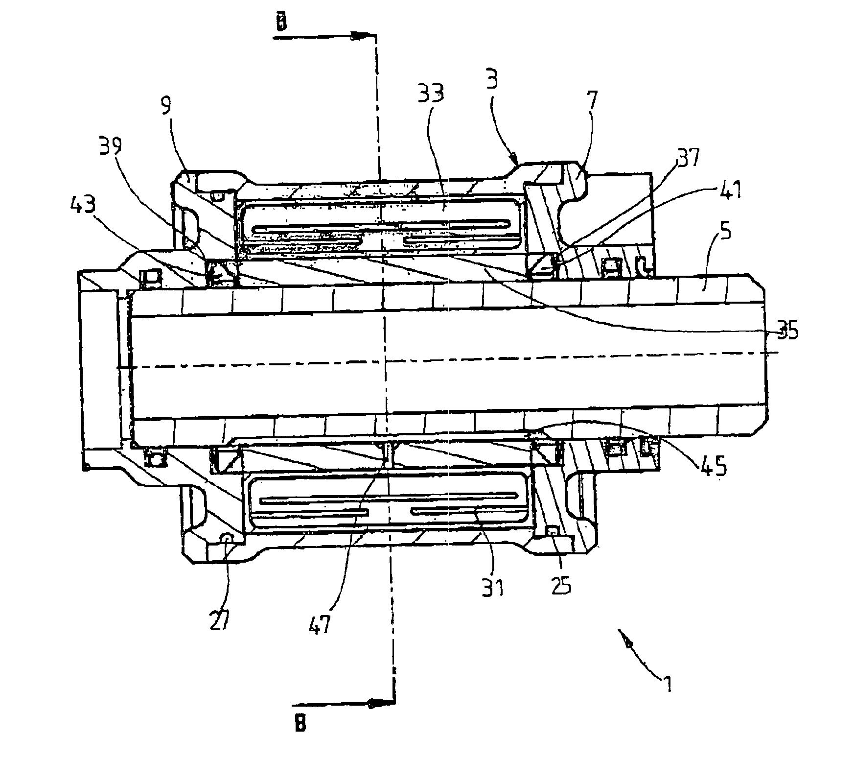
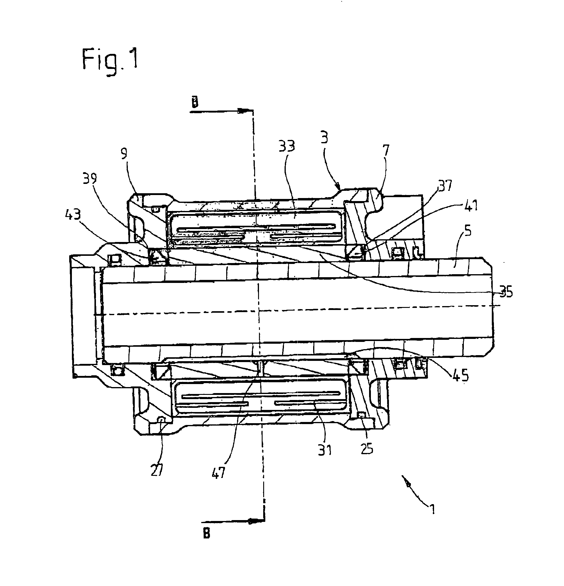
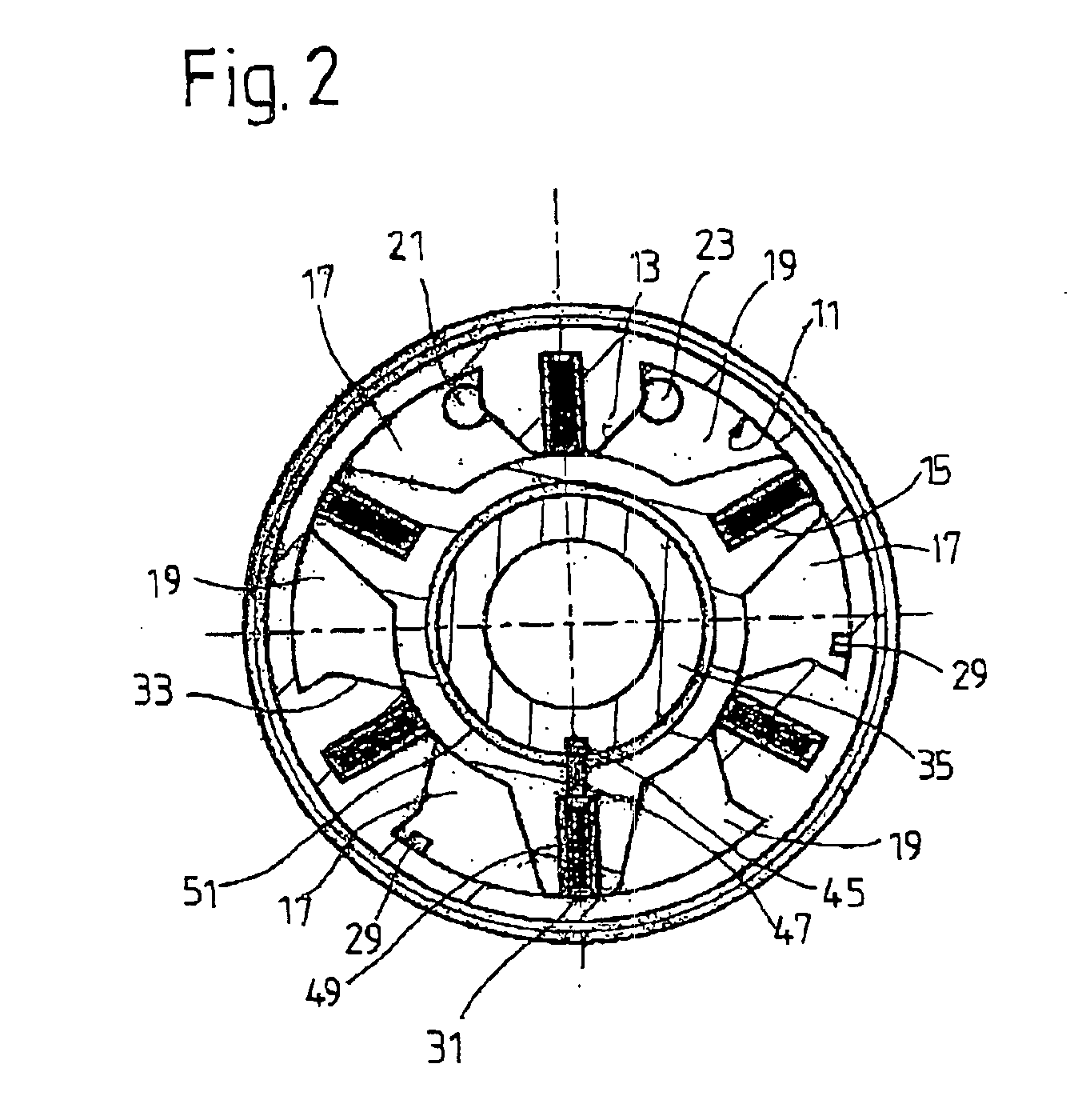
[0024]FIG. 1 shows a longitudinal section through a prime mover in the form of an oscillating motor 1 with a cylinder 3, in which a motor shaft 5 is rotatably supported. Covers 7 and 9 are welded to the ends of the cylinder 3. On the inside wall 11 of the cylinder 3, three ribs 13 (FIG. 2) are provided, which work together with the vanes 15 of the motor shaft 5, the cylinder 3, and the covers 7; 9 to form six working chambers 17; 19, where working chambers with same reference number are connected to each other by a hydraulic medium distribution system. The oscillating motor has two hydraulic connections 21; 23 (FIG. 2). A circumferential groove 25; 27 is machined into each of the two covers 7; 9. Each of these grooves has in turn an axial channel 29 (FIG. 2) leading to the assigned working chamber 17; 19. The number of working chambers depends on the torque to be developed and on the degree to which the oscillating motor can oscillate, which means that the invention is not limited t...


PUM


Abstract

An oscillating motor includes a cylinder which is filled with hydraulic medium and which has at least one rib on its inside wall, whereby a motor shaft with at least one vane is supported inside the cylinder with freedom to oscillate, a sleeve concentric to the motor shaft, and a pressure-preloaded sealing arrangement inside each of at least two ring-shaped spaces between the cylinder and the motor shaft, which sealing arrangements seal the working chambers formed by the cylinder and its rib, the motor shaft, and the vane together with the cylinder covers at the ends. The ring-shaped spaces are connected to each other by a pressure equalization channel, and an axial groove, which forms the pressure equalization channel, is present in the contact area between the motor shaft and the sleeve.

Description

BACKGROUND OF THE INVENTION[0001]1. Field of the Invention[0002]The invention relates to an oscillating motor having a cylinder with inward extending ribs, a motor shaft, outward extending vanes, a pair of cylinder covers surrounding the shaft and forming working chambers between the cylinder and the shaft, and a pressure equalization channel connecting ring shaped spaces having seals.[0003]2. Description of the Related Art[0004]A sealing arrangement of the type used in oscillating motors to seal off the motor shaft against the cylinder of the oscillating motor is known from DE 43 33 047 C1. The seal is intentionally supplied with a working pressure to achieve a dynamic preload. As a result, the advantage is obtained in an oscillating motor that, when there is no pressure in the hydraulic supply system, there is little friction between the motor shaft and the cylinder.[0005]DE 100 62 477 C1 describes taking the pressure for preloading the seal from the working spaces. For this purpo...

Claims


Application Information

Patent Timeline
Patent Type & Authority Patents(United States)
IPC IPC(8): F01C9/00F01C19/00F01C19/10
CPCF01C9/002F15B15/12F01C19/10
Inventor BEILNER, RAINERREUSS, MATTHIAS
Owner ZF SACHS AG
Why Eureka
Try Eureka