Feed screw device

Inactive Publication Date: 2005-04-19
NSK LTD
View PDF40 Cites 22 Cited by
  • Summary
  • Abstract
  • Description
  • Claims
  • Application Information

AI Technical Summary

Benefits of technology

[0060]If polyurethane rubber exceeds 80% by weight (grease is less than 20% by w

Problems solved by technology

However, particularly when the ball screw device adopting such a lubrication system directly using lubricant or grease is used in a high-temperature environment or a environment wherein wood chips, etc., easily absorbing lubricants are existed, the filled lubricant or grease flows out to the outside, is exhausted fast, and must be again supplied repeatedly for a short term.
However, with the ball screw, as the lubricant supply member containing the lubrican

Method used


Image

  • Feed screw device
  • Feed screw device
  • Feed screw device

Examples


first embodiment

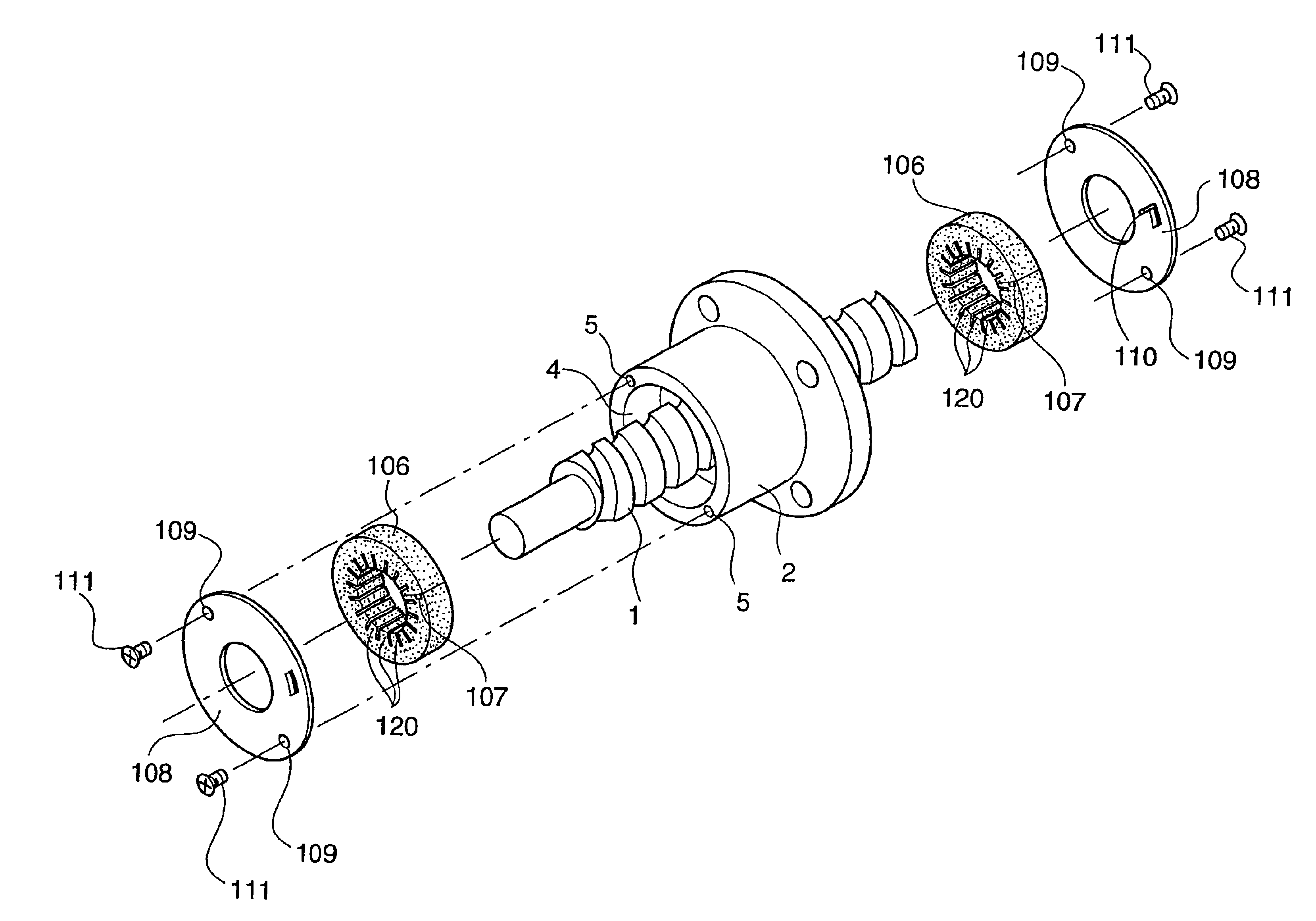
[0104]FIG. 3 is an exploded perspective view to show the main part of a ball screw according to the invention and FIG. 4 is a sectional view of the main part.

[0105]First, a general configuration of the first embodiment will be discussed. The ball screw comprises a nut member 2 threadably engaged into a screw shaft 1 having a spiral thread groove 1a on an outer peripheral surface via a large number of balls 3. The nut member 2 is formed in an inner peripheral surface with a thread groove 2a corresponding to the thread groove 1a of the screw shaft 1 and has a ball circulation passage (not shown) for guiding and circulating the balls 3 rolling in both the thread grooves 1a and 2a in a thick barrel portion.

[0106]An annular recess 4 for attaching a lubricant supply device is formed in both end faces of the inner diameter side of the nut member 2 coaxially with the nut member 2. Two tapped holes 5 are made in each of both the end faces of the nut member 2 with the axes parallel with the a...

fourth embodiment

[0154]Assembling process of the lubricant supply device will be described hereinafter.

[0155]First, the lubricant supply device 106 is fitted into a recess 4 of the nut member 2 and is inserted between the screw shaft 1 and the nut member 2. In the state, one axial end face of the lubricant supply device 6 is opposed axially to the bottom face of the recess 4 of the nut member 2 and the inner peripheral surface of the lubricant supply device 106 is opposed diametrically to the outer peripheral surface of the screw shaft 1.

[0156]Successively, the projections 110 of the fixed ring 108 are inserted into the insertion holes 107 of the lubricant supply device 106 and set screws 111 inserted into the through holes 109 are threadably engaged into the tapped holes 5 with the outer periphery of the fixed ring 108 abutted against the end of the nut member 2 coaxially, so that the fixed ring 108 is fixed to the nut member 2.

[0157]Here, the lubricant supply device 106 is formed only of a lubric...

fifth embodiment

[0181]In the fifth embodiment, the lubricant supply device 106 is engaged into the nut member 2, thus set screws are not required.

[0182]Next, a sixth embodiment of the invention will be discussed. Members identical with or similar to those previously described in the fourth embodiment are denoted by the same reference numerals in FIG. 19.

[0183]The basic configuration of a ball screw of the sixth embodiment is similar to that of the fourth embodiment, as shown in FIG. 19.

[0184]However, a plurality of lip parts 120 are provided along the circumferential direction toward the inner peripheral surface of a lubricant supply device 106, so that pilot pressure F need not be given, reducing the number of projections 110 formed on a fixed ring 108 to one.

[0185]Other components and the function and effects of the fifth embodiment are similar to those of the above-described embodiment.

[0186]However, in order to balance mounting, a set of insertion hole 107 and projection 110 may also be made at...


PUM


Abstract

A ring-like lubricant supply device 6 is fitted into a recess 4 of a nut member2. The lubricant supply device 6 contains a lubricant and is formed in an outer peripheral surface with notches 7. Tubular members 8 each having an outer diameter larger than the diameter of the notch 7 are inserted into the notches, pushing and widening the notches 7 in a circumferential direction. One end of the tubular member 8 is fitted into a recess 9b of a retaining ring 9 and the retaining ring 9 is fixed to a nut member 2.

Description

CROSS REFERENCE TO RELATED APPLICATION[0001]This is a division of application Ser. No. 08 / 877,518 (Confirmation No. 6133) filed Jun. 17, 1997, now U.S. Pat. No. 6,338,285 the disclosure of which is incorporated herein by reference.BACKGROUND OF THE INVENTION[0002]This invention relates to a feed screw device of a ball screw, square thread, etc. Particularly, the invention relates to a feed screw device that can automatically supply a lubricant over a long term.[0003]A conventional ball screw, a kind of feed screw device, is described in Japanese Utility Model Unexamined Publication Nos. Hei 7-4952 and 6-47762, etc., for example.[0004]This kind of ball screw comprises a spiral thread groove 50a made in the outer peripheral surface of a screw shaft 50 threadably engaging a spiral thread groove 51a made in the inner peripheral surface of a nut member 51 via a plurality of balls 52, as shown in FIG. 1, for converting relative rotation of the screw shaft 50 to the nut member 51 into rela...

Claims


Application Information

Patent Timeline
IPC IPC(8): F16H25/24F16H57/04
CPCF16H25/2418F16H57/0406F16H57/0497Y10T74/1527Y10T74/18744Y10T74/19744Y10T74/19991Y10T74/18712Y10T74/19702F16H25/2204
Inventor TSUKADA, TORUKATO, SOICHIRO
Owner NSK LTD
Why Eureka
Try Eureka