High intensity photocuring system

a high-intensity, photocuring technology, applied in the direction of optical radiation measurement, printers, instruments, etc., can solve the problems of damage or defect, collection lens does not properly focus non-collimated light exiting the led array, etc., to achieve the effect of increasing the intensity

Inactive Publication Date: 2005-04-19
SMD SOFTWARE
View PDF17 Cites 227 Cited by
  • Summary
  • Abstract
  • Description
  • Claims
  • Application Information

AI Technical Summary

Benefits of technology

[0011]In another embodiment, the photocuring assembly includes a redirecting assembly disposed between the collection lens and the desired location. Due to the emission properties of conventional LEDs, the LED assembly may not collimate some minority of the light. As a result, the c...

Problems solved by technology

In addition, damaged or defective LED inserts and/or assemblies may be replaced without necessitating the replacement of...

Method used


Image

  • High intensity photocuring system
  • High intensity photocuring system
  • High intensity photocuring system

Examples


Embodiment Construction

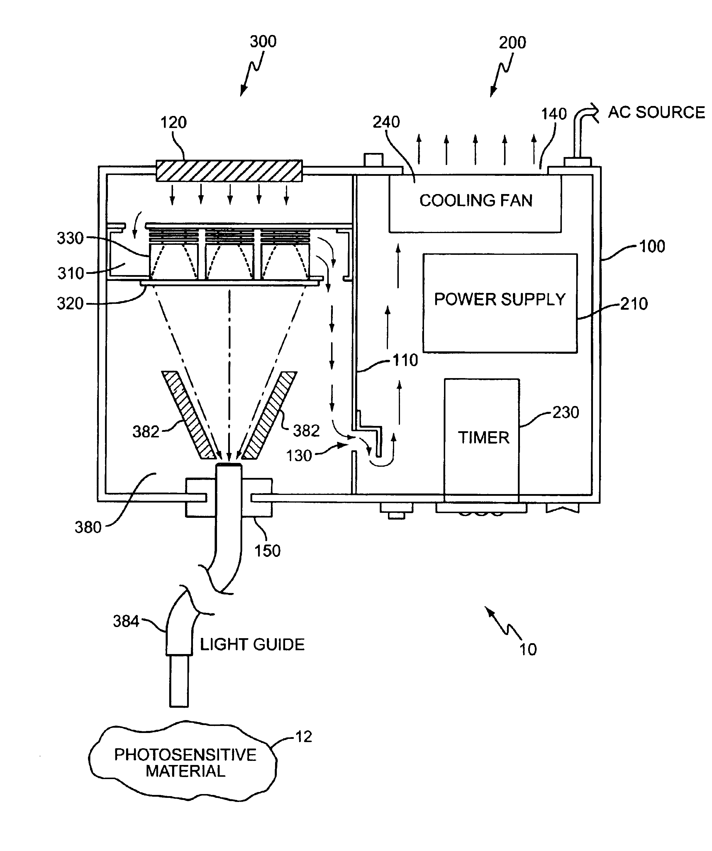
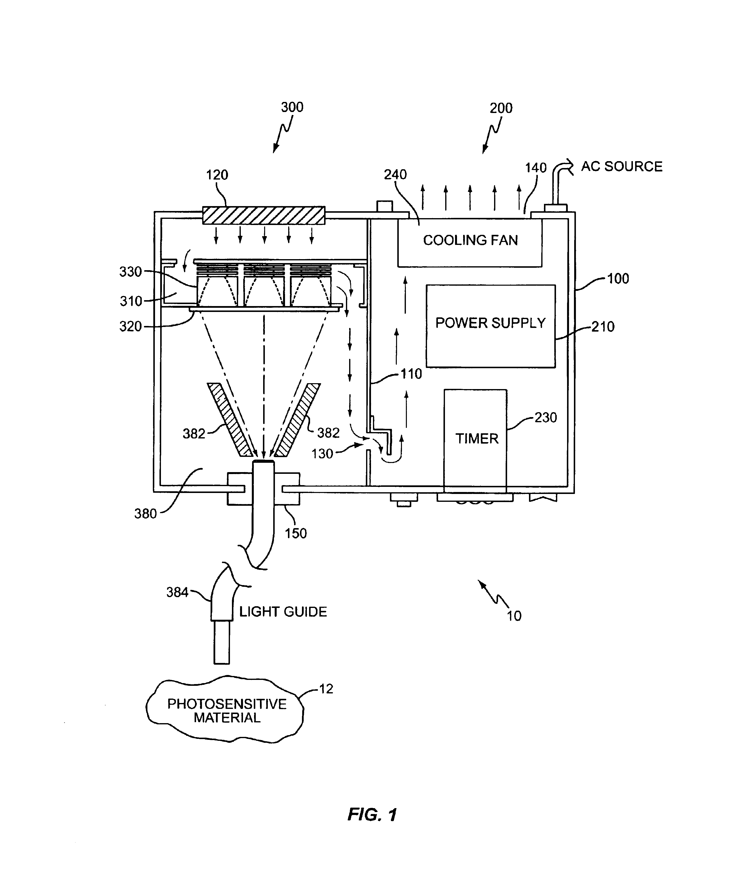
[0022]The present invention relates to a photocuring system that intensifies light emitted from one or more LEDs. The intensified light may be delivered to a remote location to induce a change in a photosensitive material 12 at the remote location, such as to cure the photosensitive material 12. Because one application for the present invention is curing UV curable materials, the discussions below use UV LEDs to illustrate the invention. However, it should be understood that the present invention is not limited to UV light or UV photocuring technologies.

[0023]An exemplary photocuring system according to the present invention, generally indicated at 10, is shown in FIGS. 1-8. The photocuring system 10 includes an electrical assembly 200 and an optical assembly 300, both enclosed in a suitable housing 100. In addition to providing the mechanical structure, the housing 100 also provides a safety feature by isolating any potentially hazardous optical energy from a user. As shown in FIG....


PUM


Abstract

A method and apparatus for curing photosensitive materials uses LEDs and an optical concentrator to generate high optical power intensities. An LED array, comprising a plurality of LED assemblies, generates collimated light. A collection lens functions as an optical concentrator and focuses the collimated light to a desired spot size at a desired location. The LED assemblies may be at least partially disposed in a cooling plenum, where the cooling plenum is at least partially defined by the collection lens. Each LED assembly within the LED array may be detachably coupled to a mounting surface, enabling easy replacement of individual LED assemblies within the LED array. The photocuring assembly may also include a redirecting assembly disposed between the collection lens and the desired location that may further concentrate the light at the desired location. The photocuring assembly may include more than one of the above features.

Description

BACKGROUND OF THE INVENTION[0001]The present invention generally relates to a method and apparatus for curing photosensitive materials, and more particularly to a method and apparatus for intensifying and routing light, such as ultra-violet light, generated by light emitting diodes for the purpose of curing photosensitive materials.[0002]One typical environment where photosensitive curing technology is encountered is in the curing of ultra-violet (UV) photosensitive materials during the manufacture of electronic components. The photocuring systems found in such environments typically use mercury-arc lamps to flood the UV sensitive material with UV light. While mercury-arc lamp technology is widely used, such technology has several disadvantages. The most obvious disadvantage is the life span of the mercury bulbs used in the mercury-arc lamps. Mercury bulbs have a relatively short life, typically 100-1000 hours. Further, the mercury bulb degrades nonlinearly during its lifetime. As a...

Claims


Application Information

Patent Timeline
IPC IPC(8): A61C13/15A61C13/00
CPCA61C19/004Y10S362/80
Inventor OLLETT, SCOTT H.LAMPE, JR., ROSS W.
Owner SMD SOFTWARE
Why Eureka
Try Eureka