Casing, a compressor, a turbine, and a combustion turbine engine including such a casing

a combustion turbine engine and compressor technology, applied in the direction of liquid fuel engines, machines/engines, efficient propulsion technologies, etc., can solve the problems of reducing affecting the service life of the bleed or unloader valve, so as to avoid excessive energy loss

Active Publication Date: 2005-04-19
SN DETUDE & DE CONSTR DE MOTEURS DAVIATION S N E C M A
View PDF12 Cites 32 Cited by
  • Summary
  • Abstract
  • Description
  • Claims
  • Application Information

AI Technical Summary

Benefits of technology

[0011]An object of the present invention is to provide a casing enabling the use of bleed or unloader valves to be avoided or minimized, while nevertheless avoiding excessive energy loss.
[0012]An object of the invention is thus to enable the surging phenomenon to be reduced locally by increasing the present surging margin, but without reducing the efficiency of the engine.

Problems solved by technology

Surging is a phenomenon within the engine that should be avoided since it involves sudden oscillations in air pressure or air flow rate, thereby subjecting the blades to considerable levels of mechanical stress that can cause them to be weakened or even broken.
Nevertheless, such bleed or unloader valves are relatively expensive and fragile, and require an electrical power supply and strict maintenance.
Proposals have also been made to pierce the casing so as to form controlled leaks: nevertheless, that solution is very harmful in terms of energy efficiency since it puts the air stream directly into communication with the outside of the filament of flow.

Method used


Image

  • Casing, a compressor, a turbine, and a combustion turbine engine including such a casing
  • Casing, a compressor, a turbine, and a combustion turbine engine including such a casing
  • Casing, a compressor, a turbine, and a combustion turbine engine including such a casing

Examples


Embodiment Construction

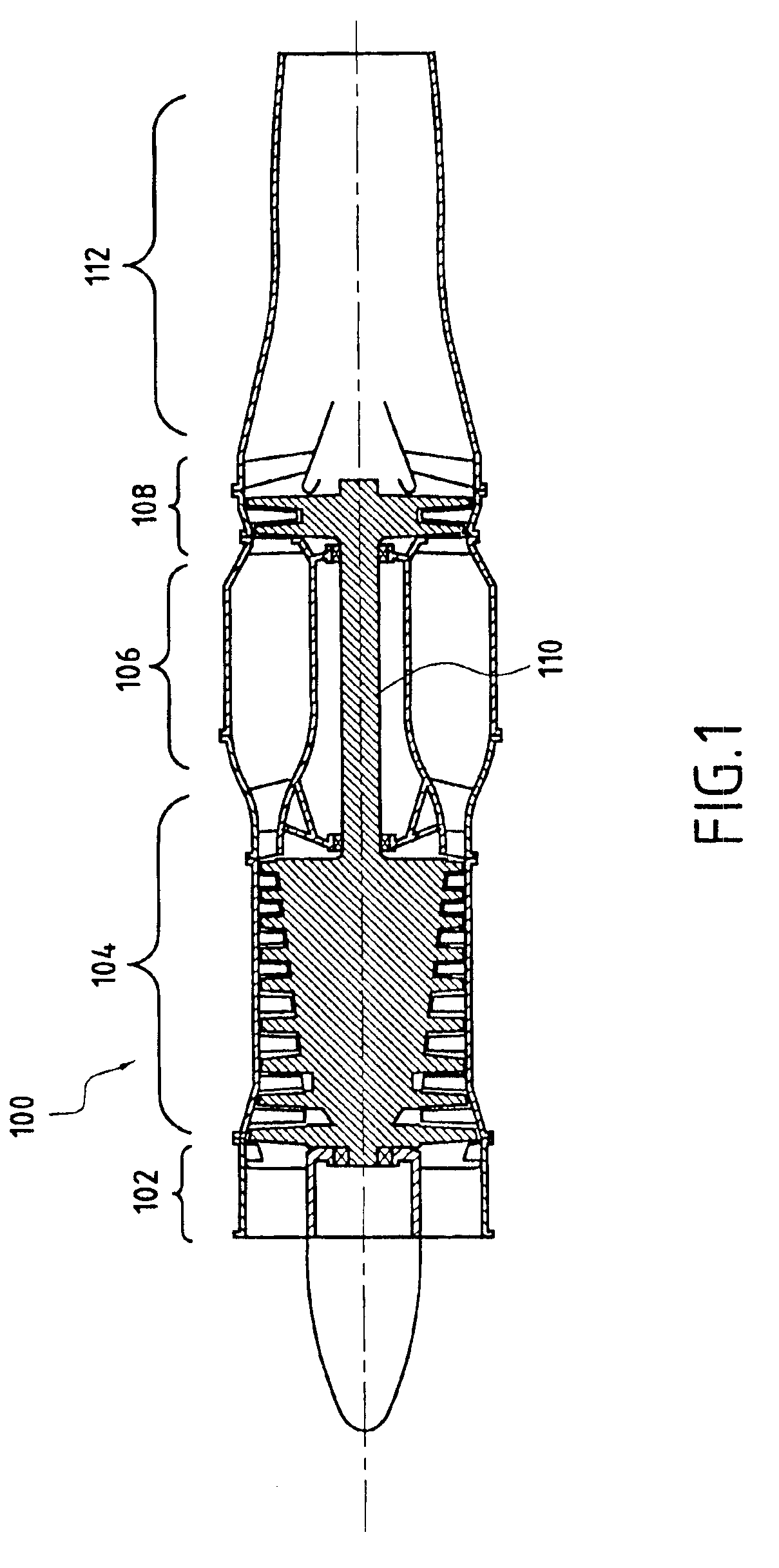
[0034]As can be seen in FIG. 1 which is a diagram of an axial turbojet engine 100 with its moving parts shaded, the main members of the turbojet engine comprise, from the upstream end to the downstream end: a fan 102, a compressor 104, a combustion chamber 106, a turbine 108 fitted with its shaft 110, and an exhaust duct 112.

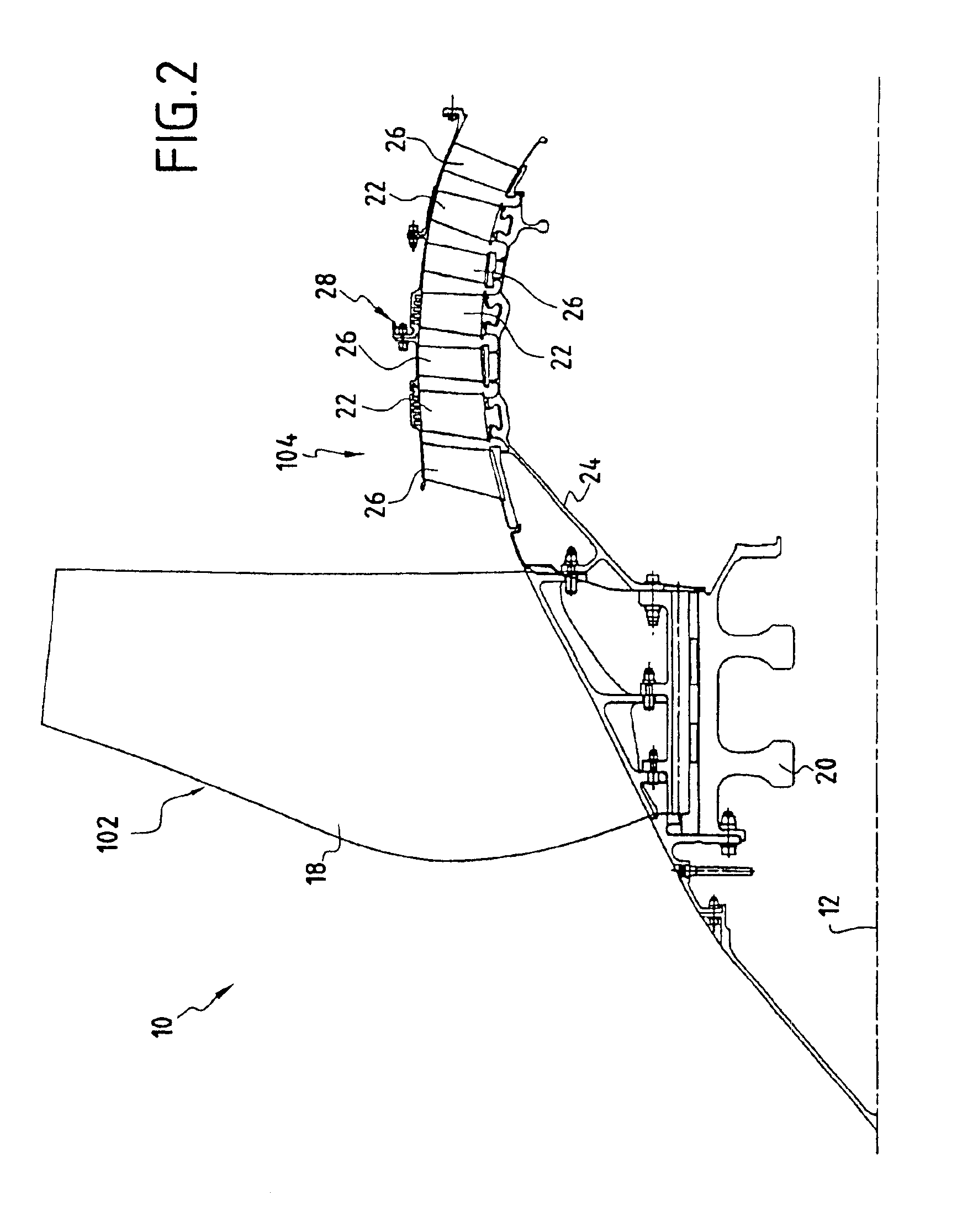
[0035]FIG. 2 shows a portion of FIG. 1 on a larger scale.

[0036]More precisely, FIG. 2 is a section through half of the front portion 10 of a turbojet engine of the same kind as shown in FIG. 1, this half being situated on one side of the longitudinal axis 12 forming the axis of symmetry about which various elements rotate, in particular the various moving elements of the turbojet engine.

[0037]More precisely, amongst the various elements disposed axially around the longitudinal axis 12 and forming the conventional structure of such a turbojet engine, FIG. 2 shows the fan 102 and the compressor 104 that operates at low pressure.

[0038]The fan 102 comprises a series...


PUM


Abstract

The casing of the invention is of the type supporting series of stationary blades having disposed between them series of blades that are movable in rotation about a longitudinal axis. In characteristic manner, said casing comprises a main element and, at least facing one of the series of moving blades, an assembly comprising a plate made of a honeycomb material and a covering disposed on the face of the plate facing away from the blades so that said cells are open towards the blades, said covering being provided with holes that open out into cells of the plate, thereby forming open cells, said covering closing other cells of the plate, thereby forming closed cells, a cavity being formed between said plate and the inside face of said main element. Preferably, the casing forms the casing of an axial compressor operating at low pressure in a turbojet engine.

Description

[0001]The invention relates to a casing supporting a series of stationary blades between which there are disposed series of moving blades rotatable about a longitudinal axis, the radially outer ends of said moving blades being close to the inside face of the casing, in particular a casing used for an aviation turbojet engine.[0002]The invention also relates to making a compressor, in particular of the axial type, specifically a compressor operating at low pressure and including a casing as mentioned above.BACKGROUND OF THE INVENTION[0003]Compressors of this type are used in particular in turbojet engines and are constituted by a rotor comprising either a succession of separate disks that are stacked one after another, or else a single drum designed to receive the series of blades constituting the various stages.[0004]Conventionally, the rotor includes recesses or retention grooves that are made by machining in order to form spaces between pairs of adjacent stages in which the blades...

Claims


Application Information

Patent Timeline
Patent Type & Authority Patents(United States)
IPC IPC(8): F04D27/02F01D11/08F01D5/14F01D11/12F04D29/08F04D29/68F04D29/16F04D29/66F01D11/02F01D9/00F01D25/24F02C7/28F04D29/52
CPCF01D5/145F01D11/125F04D27/0207F04D29/164F04D29/685F04D29/526Y02T50/673F05D2220/36Y02T50/672Y02T50/60
Inventor LE BIEZ, PHILIPPELEBRET, YANNMONS, CLAUDE
Owner SN DETUDE & DE CONSTR DE MOTEURS DAVIATION S N E C M A
Why Eureka
Try Eureka