Magnetic recording medium including functional and recording layers orthogonally exchange coupled

a recording layer and functional technology, applied in special recording techniques, maintaining head carrier alignment, instruments, etc., can solve the problems of inability to maintain the domain, inability to record magnetically, physical limitations, etc., to achieve the effect of increasing the effective volume of the magnetic reversal unit, reducing thermal fluctuations, and doubling the recording density

Inactive Publication Date: 2005-04-19
KK TOSHIBA
View PDF13 Cites 40 Cited by
  • Summary
  • Abstract
  • Description
  • Claims
  • Application Information

AI Technical Summary

Benefits of technology

[0010]In the recording medium having the above-summarized configuration, the recording layer and the functional layer magnetically reverse independently from each other, while the recording layer and the functional layer are magnetically continuous. This results in increasing the effective volume of the magnetization reversal unit of the recording layer and alleviation of thermal fluctuation. At the same time, by recording information in both the recording layer and the functional layer, so-called dual-value recording is enabled, which results in doubling the recording density.

Problems solved by technology

Increase of the density, however, is physically limited, and this is an issue whether the techniques can continuously meet such request or not.
However, if the magnetization reversal unit is diminished, then the magnetic anisotropy energy of the unit (Ku (density of magnetically anisotropy energy)×V (volume of the magnetization reversal unit)) becomes smaller than the thermal fluctuation energy, and it will be no longer possible to maintain the domains.
However, since the recording coercivity Hcw is approximately proportional to Ku, magnetic recording is impossible even by the state-of-art recording head, which can generate the highest magnetic field in the world.
However, increase of the size of magnetic grain along the plane of the medium is against the requirement of the high-density recording.
In addition, when V is increased by increasing the thickness of the medium, the recording field from the head cannot reach a full-depth of the medium and fails to reverse the magnetization.
Here again, high-density recording is not possible.
As discussed above, conventional magnetic recording mediums involve the problem that enhancement of the density encounters a limit caused by the thermal fluctuation phenomenon.

Method used


Image

  • Magnetic recording medium including functional and recording layers orthogonally exchange coupled
  • Magnetic recording medium including functional and recording layers orthogonally exchange coupled
  • Magnetic recording medium including functional and recording layers orthogonally exchange coupled

Examples


first example

[0234]As the first example of the invention, detailed explanation is given below about an experiment for confirming the effect of preventing thermal fluctuation by orthogonal exchange coupling interaction in a structure including a spacer layer between the functional layer and the recording layer.

[0235]In this example, a magnetic recording medium having the cross-sectional structure shown in FIG. 8 was prepared.

[0236]More specifically, after depositing a 50 nm thick Pt under layer on a glass substrate (13) of 3.5 inches in diameter, and sequentially depositing thereon a 15 nm thick FePt—B functional layer (12), 0.4 nm thick Mn spacer layer (71), 15 nm thick CoPtCr recording layer (11) and 3 nm thick C protective layer (14), a lubricant was coated on the surface. Upon forming the FePt—B functional layer (12) the substrate was heated to approximately 400° C. As a result of this heating process, orientation of the magnetic anisotropy of the functional layer (12) stood up by 45 degrees ...

second example

[0253]As the second example of the invention, explanation will be next made about results of an experiment conducted by setting in-plane magnetic anisotropy to each of the functional layer and the recording layer by using two under layers.

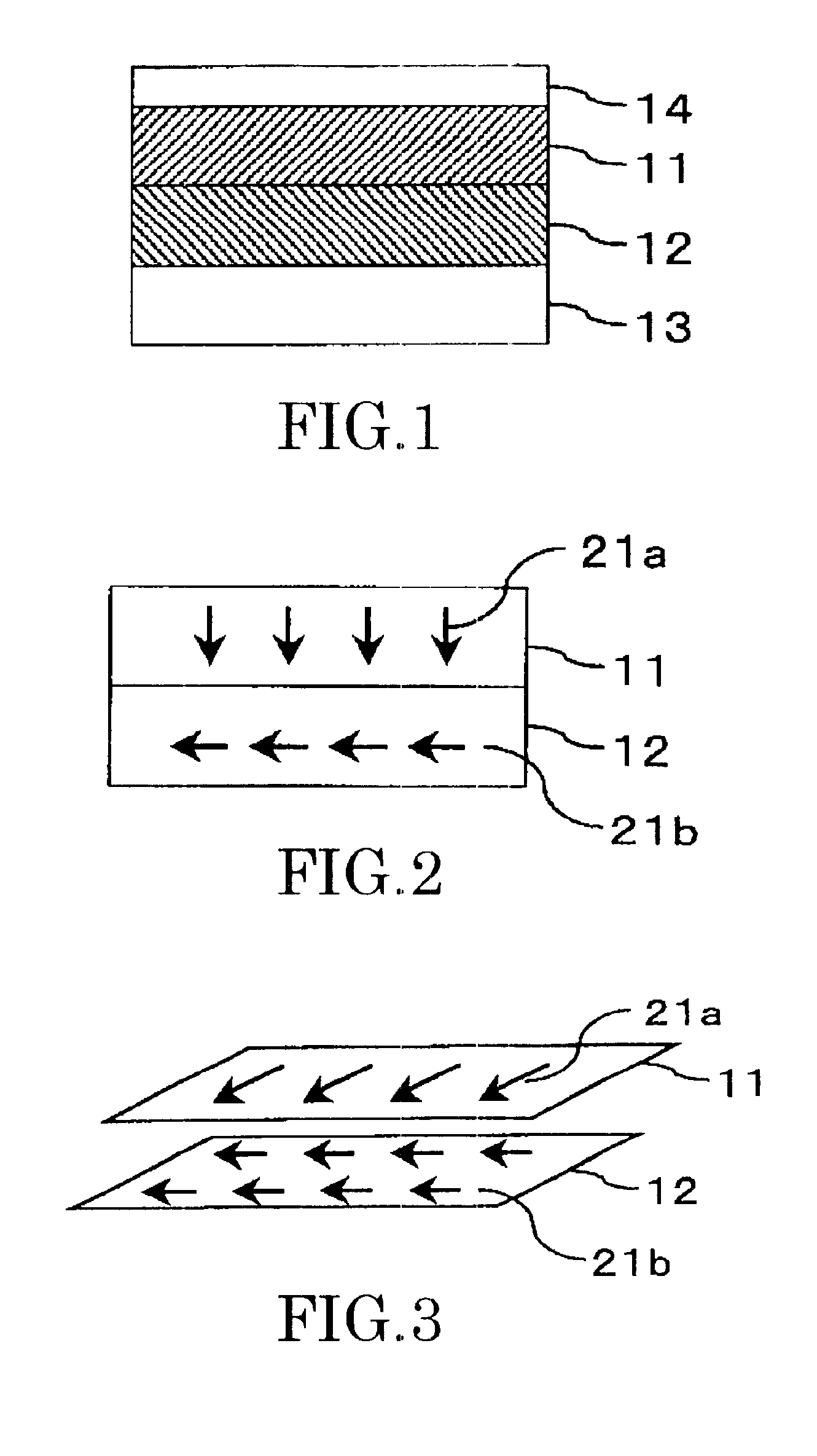
[0254]In this example, a magnetic recording medium having the multi-layered structure shown in FIG. 1 was prepared. More specifically, on a NiP-plated Al disk substrate (13) of 3.5 inches, a 50 nm thick Ti first under layer, 30 nm thick NiAl second under layer, 10 nm thick CoCrPtTa functional layer (12), 10 nm thick CoCrPtTa recording layer (11) and 3 nm thick C protective layer (14) were sequentially deposited by sputtering, and a lubricant was coated thereafter. All layers were formed consecutively without breaking the vacuum.

[0255]Although a 0.2 nm thick Pt spacer layer was deposited between the functional layer (12) and the recording layer (11), existence of the Pt spacer layer could not confirmed by cross-sectional TEM probably because the Pt ...

third example

[0266]As the third example of the invention, explanation will be next made about results of trial preparation of a recording medium having a spacer layer between the functional layer and the recording layer and trial preparation of a magnetic recording apparatus having mounted the recording medium.

[0267]In this example, a magnetic recording medium having the cross-sectional structure shown in FIG. 8 was prepared. More specifically, on a NiP-plated Al disk substrate (13) of 3.5 inches, a 50 nm thick Ti first under layer, 30 nm thick NiAl second under layer, 10 nm thick CoCrPtTa functional layer (12), 1 nm thick Rh spacer layer (71), 10 nm thick CoCrPtTa recording layer (11) and 3 nm thick C protective layer (14) were sequentially deposited by sputtering, and a lubricant was coated thereafter.

[0268]Here again, all layers were formed consecutively without breaking the vacuum. However, before forming the under layers, the substrate was treated by texturing process to give anisotropy in ...


PUM

PropertyMeasurementUnit
thicknessaaaaaaaaaa
thicknessaaaaaaaaaa
thicknessaaaaaaaaaa

Abstract

A magnetic recording medium capable of alleviating thermal fluctuation and improving the recording density includes a functional layer (12) containing a magnetic material, and a recording layer (11) overlying the functional layer and containing a magnetic material. The recording layer contains a plurality of magnetic grains (51) and a nonmagnetic material (52) existing among the magnetic grains, and the functional layer and the recording layer exert exchange coupling interaction in a direction making a substantially orthogonal relation with each other at the room temperature.

Description

CROSS-REFERENCE TO RELATED APPLICATIONS[0001]This application is based upon and claims the benefit of priority from the prior Japanese Patent Application No. 2001-197771, filed on Jun. 29, 2001; the entire contents of which are incorporated herein by reference.BACKGROUND OF THE INVENTION[0002]This invention relates to a magnetic recording medium, magnetic recording apparatus and magnetic recording method, and more particularly, to a magnetic recording medium, magnetic recording apparatus and magnetic recording method capable of higher-density recording than conventional recording by suppressing thermal fluctuation.[0003]Along with recent progress of computers in processing speed, there is a continuous demand on higher speeds and higher densities also of hard disk drives (HDDs). Increase of the density, however, is physically limited, and this is an issue whether the techniques can continuously meet such request or not.[0004]Magnetic recording mediums for substantially recording info...

Claims


Application Information

Patent Timeline
Patent Type & Authority Patents(United States)
IPC IPC(8): G11B5/00G11B5/66G11B5/39G11B5/596G11B5/012G11B5/48G11B5/65G11B5/02G11B5/265G11B5/64G11B5/738G11B7/00G11B11/10H01F10/30
CPCB82Y10/00G11B5/00G11B5/02G11B5/1278G11B5/3916G11B5/3925G11B5/59683G11B5/66G11B5/743G11B5/746G11B5/82B82Y25/00Y10T428/31G11B5/012G11B5/488G11B7/00G11B2005/0002G11B2005/0005G11B2005/0021G11B2005/3996Y10T428/24942
Inventor KIKITSU, AKIRAKAI, TADASHIAKIYAMA, JUNICHI
Owner KK TOSHIBA
Why Eureka
Try Eureka