
On-chip high-pass filter with large time constant

a high-pass filter and time constant technology, applied in the field of high-pass filters, can solve the problems of not being able to directly connect signals from one power supply domain to another, the working voltage on the chip has been greatly reduced, and the dc voltage level shifter is actually too low to meet the original performance requirements, and achieves the effect of large time constan

Inactive Publication Date: 2005-04-19
REALTEK SEMICON CORP
View PDF5 Cites 33 Cited by
  • Summary
  • Abstract
  • Description
  • Claims
  • Application Information

AI Technical Summary

Benefits of technology

[0008]It is therefore a primary objective of the claimed invention to provide an on-chip high-pass filter having a low corner frequency and a large time constant to solve the above-mentioned problem.
[0009]According to the claimed invention, an on-chip high-pass filter with large time constant comprising a capacitor, a first transistor having a first terminal connected to a first voltage source and a second terminal connected to the capacitor, and a second transistor having a first terminal connected to the second terminal of the first transistor and a second terminal connected to ground, wherein the first transistor and the second transistor are for operating as a large-resistance resistor. The electrical equivalent large-resistance resistor and the capacitor together form a high-pass filter between the input port and the output port.

Problems solved by technology

In a device using two separate supply voltages, it may not be possible to directly connect signals from one power supply domain to another due to different DC voltage levels.
However, due to improvements in the IC and device fabrication process, the on-chip working voltage has been greatly reduced and is actually too low for a DC voltage level shifter to meet its original performance requirements.
If not removed, this unwanted DC offset voltage could saturate sensitive devices, such as ADC converters, causing them to malfunction.
A DC servo circuit uses feedback to hold the output DC voltage level constant, however, the smaller the feedback window is (meaning a very low corner frequency), the longer the settling time will be.
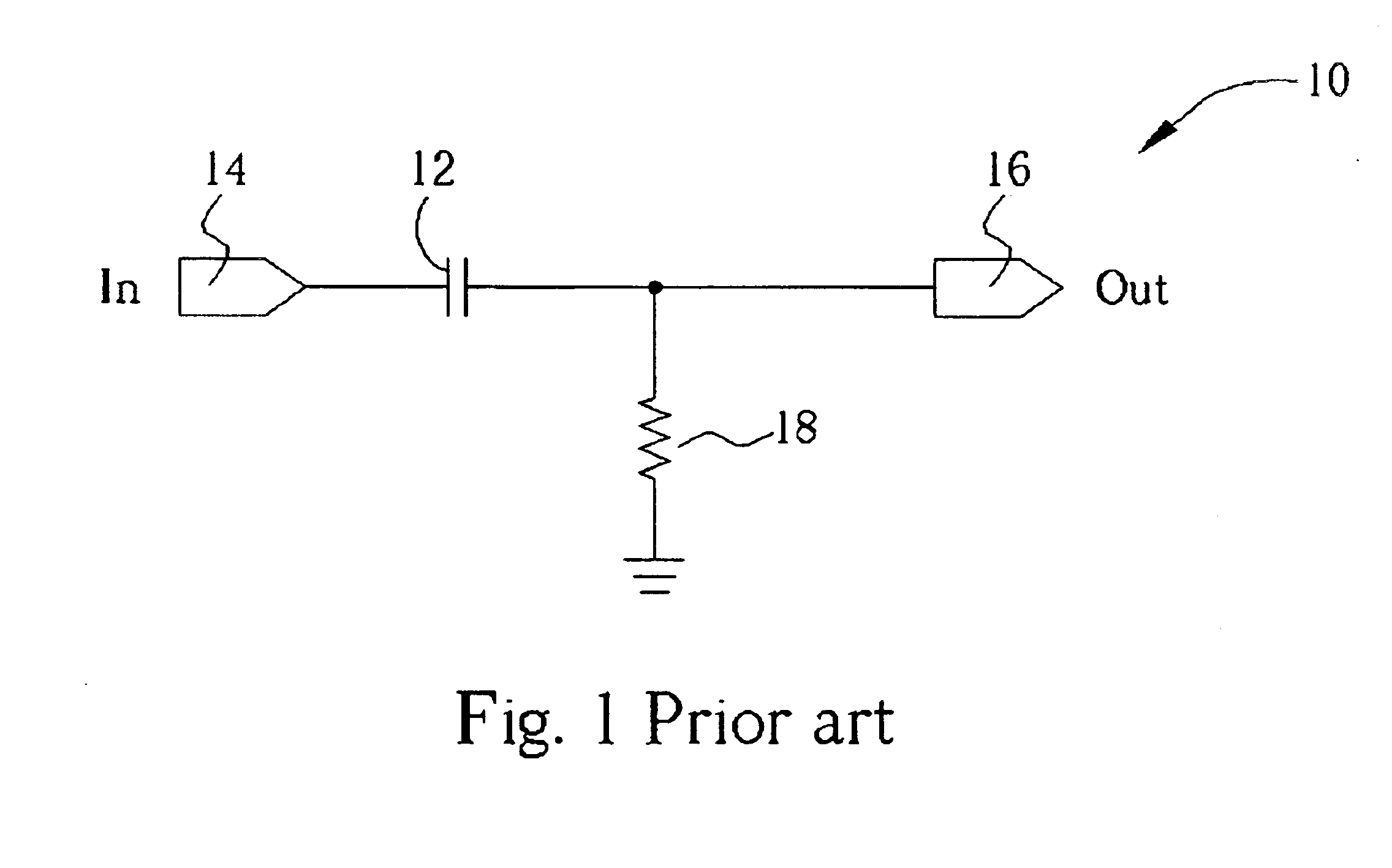
When the corner frequency is very low, not only are the resistance of the resistor and the capacitance of the capacitor of the required filter very large but also the settling time is often too long.
These large-magnitude resistors and capacitors are very difficult to implement on an IC without using extremely large amounts of IC space.

Method used


Image

  • On-chip high-pass filter with large time constant
  • On-chip high-pass filter with large time constant
  • On-chip high-pass filter with large time constant

Examples


Embodiment Construction

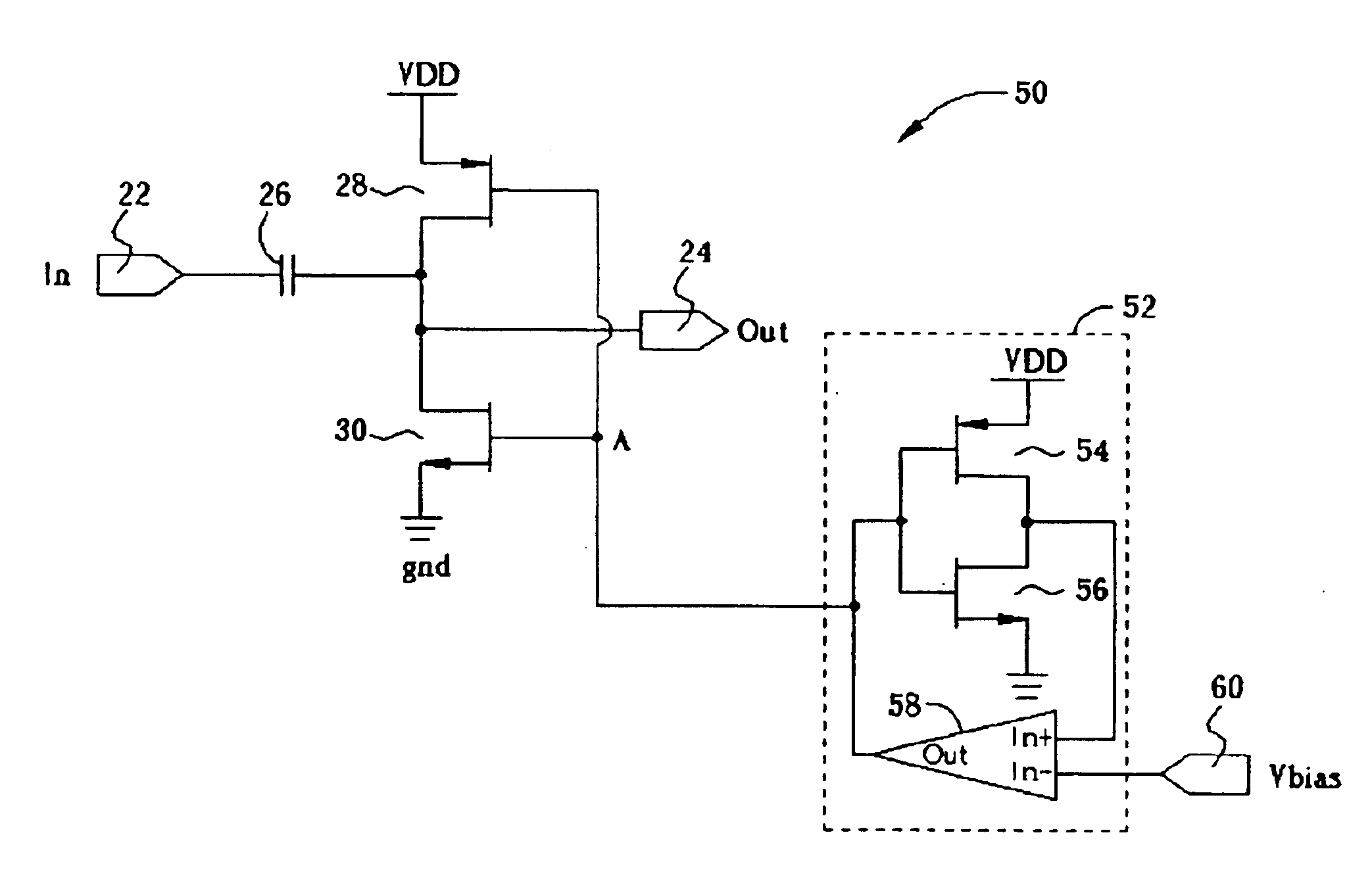
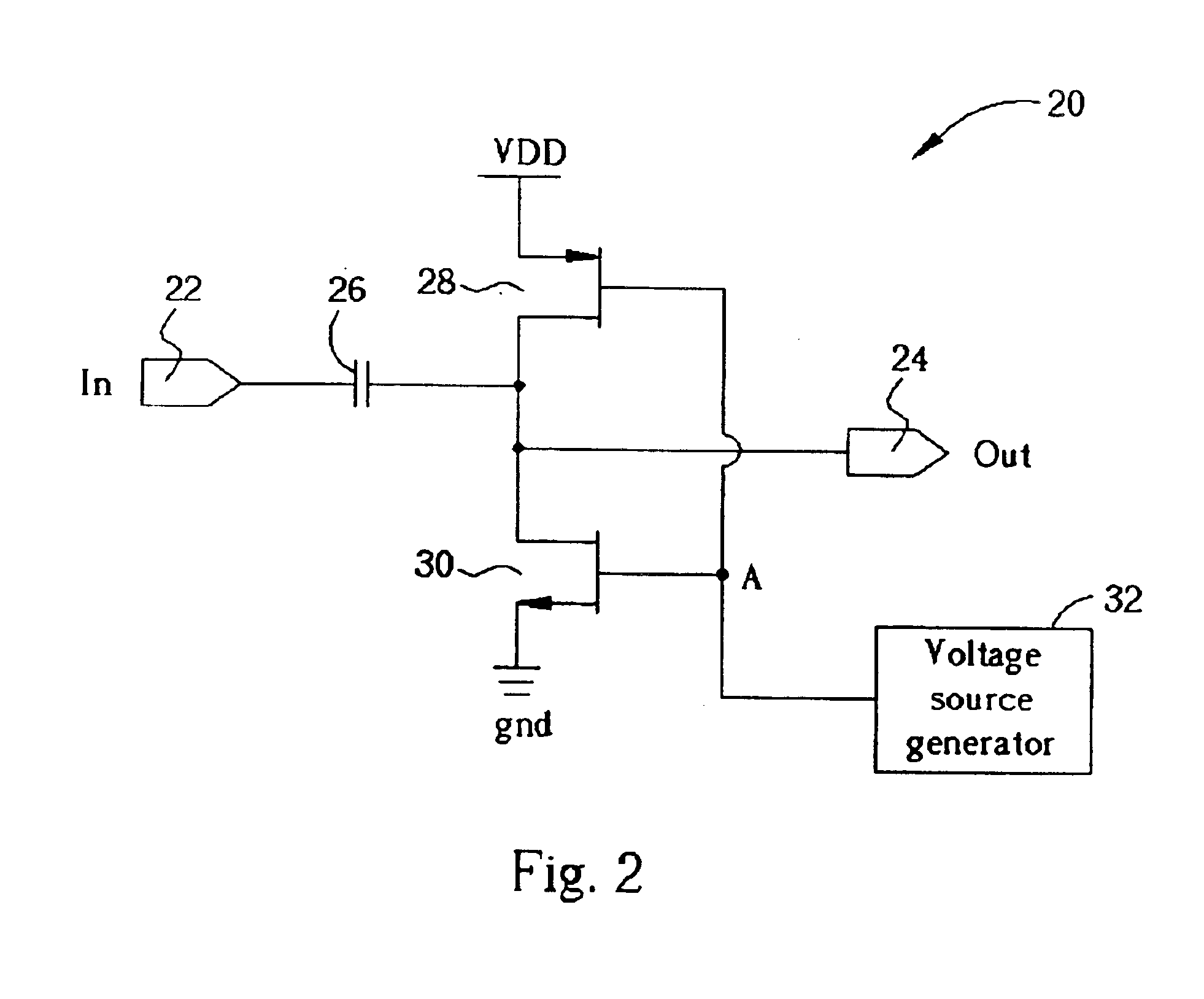
[0018]Please refer to FIG. 2 showing a schematic diagram of a high-pass filter 20 according the embodiment of the present invention. The high-pass filter 20 comprises an input port 22, an output port 24, a capacitor 26, a p-type transistor 28, an n-type transistor 30, and a voltage source generator 32. The capacitor 26 is connected between the input port 22 and the output port 24. The p-type transistor 28 has its source terminal connected to a supply voltage VDD and its drain terminal connected to the output port 24. The n-type transistor 30 has its drain terminal connected the output terminal 24 and its source terminal connected to ground. The gate terminals of both the p-type transistor 28 and n-type transistors 30 are connected to the output of the voltage source generator 32. The voltage source generator 32 is for providing a voltage level such that both the p-type transistor and the n-type transistor can be operated in a saturation mode.

[0019]The magnitude of the drain current ...


PUM


Abstract

An on-chip high-pass filter with large time constant comprising a capacitor, a first transistor having a first terminal connected to a first voltage source and a second terminal connected to the capacitor, and a second transistor having a first terminal connected to the second terminal of the first transistor and a second terminal connected to ground, wherein the first transistor and the second transistor are for operating as a large-resistance resistor. The electrical equivalent large-resistance resistor and the capacitor together form a high-pass filter between the input port and the output port.

Description

BACKGROUND OF INVENTION[0001]1. Field of the Invention[0002]The invention relates to a high-pass filter, and more particularly, to an on-chip high-pass filter with a large time constant.[0003]2. Description of the Prior Art[0004]In order to remove the DC component of a signal or to eliminate the DC offset, many circuits call for the use of a high-pass filter. A DC voltage blocking capacitor, DC voltage level shifter, and DC servo loop are all the example circuits implemented as high-pass filters.[0005]In a device using two separate supply voltages, it may not be possible to directly connect signals from one power supply domain to another due to different DC voltage levels. In order to connect signals between the two domains, a DC voltage level shifter can be used to shift the voltage from the first domain to that of the second domain. However, due to improvements in the IC and device fabrication process, the on-chip working voltage has been greatly reduced and is actually too low fo...

Claims


Application Information

Patent Timeline
Patent Type & Authority Patents(United States)
IPC IPC(8): H03H11/04
CPCH03H11/04
Inventor KANG, HAN-CHANG
Owner REALTEK SEMICON CORP
Learn More