Harmonic neutralized frequency changer

a frequency changer and neutralization technology, applied in the field of frequency changer circuits, can solve the problems of affecting system efficiency and power density reduction, and affecting the conversion process, so as to achieve the effect of reducing the loss of applied power from 2-3% of the applied power

Active Publication Date: 2005-04-19
CURTISS WRIGHT ELECTRO MECHANICAL
View PDF11 Cites 24 Cited by
  • Summary
  • Abstract
  • Description
  • Claims
  • Application Information

AI Technical Summary

Problems solved by technology

However, the efficiency and power density of this technology is limited by the need for two to three stages of power conversion.
These multistage conversions hinder system efficiency and lower power density.
For example, the losses in the conversion processes typically range from 2-3% of applied power.
In many applications, these losses are not acceptable.
For example, any wasted power in “onboard” or self-sustained systems such as ships and submarines significantly decreases propulsion system performance.

Method used


Image

  • Harmonic neutralized frequency changer
  • Harmonic neutralized frequency changer
  • Harmonic neutralized frequency changer

Examples


Embodiment Construction

[0021]It is to be understood that the figures and descriptions of the present invention have been simplified to illustrate elements that are relevant for a clear understanding of the invention, while eliminating, for purposes of clarity, other elements that may be well known. Those of ordinary skill in the art will recognize that other elements are desirable and / or required in order to implement the present invention.

[0022]However, because such elements are well known in the art, and because they do not facilitate a better understanding of the present invention, a discussion of such elements is not provided herein. The detailed description will be provided hereinbelow with reference to the attached drawings.

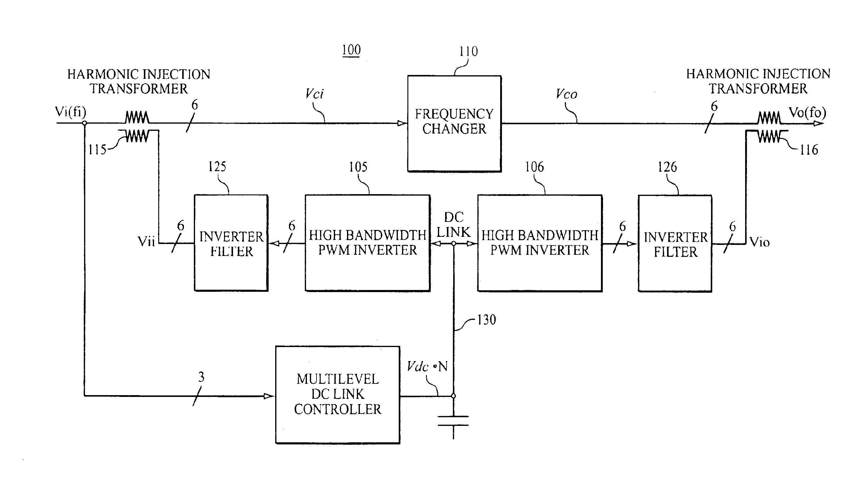
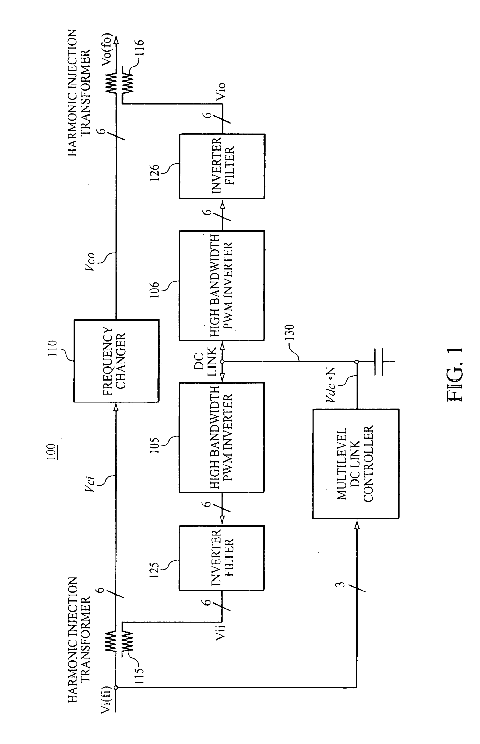
[0023]In at least one preferred embodiment, the present invention comprise a novel system architecture that will reduce system losses in electric motors to less than 1% and increase the power density by a factor of 3 to 6 times better than basic multilevel PWM power converters. T...


PUM


Abstract

A power converter that produces variable frequency multiphase AC power from fixed or variable frequency AC power. The converter can be used to drive an AC motor for propulsion applications or other motors and loads that require variable frequency AC power. The power converter system is based on a combination of several power conversion technologies used in a power circuit topology and a regulator control system that allows for higher electrical efficiency, higher power density and lower power distortion to be achieved than is possible from any of the individual technologies. Specifically, the input and output power distortion of a frequency changer is monitored, and a group of high performance inverters are used to inject harmonic currents into a specially designed transformer to neutralize the power distortion to a specified acceptable level. By this neutralization, the power density of a solid-state electric power converter is increased (e.g., by a factor of 5-6) and power quality distortion is reduced (e.g., below 0.1%). These features are especially useful in the electric power conversion markets particularly for surface ship and submarine propulsion drive applications.

Description

BACKGROUND OF THE INVENTION[0001]1. Field of the Invention[0002]The present invention relates generally to frequency changer circuits for electric motor systems, and more specifically, the present invention relates to the calculation, generation, application and control of currents to neutralize unwanted harmonic frequencies in conventional frequency changer circuits.[0003]2. Description of the Background[0004]In many diverse environments, electric motors are used as drive or propulsion systems. The requirement for low noise and low distortion power conversion systems has made the multilevel PWM (pulse width modulation) technology a strong contender for many different electric motor drive applications. However, the efficiency and power density of this technology is limited by the need for two to three stages of power conversion. Specifically, power must first be converted from AC to DC and then from DC back to AC by accommodating the PWM technology.[0005]These multistage conversions...

Claims


Application Information

Patent Timeline
Patent Type & Authority Patents(United States)
IPC IPC(8): H02M5/02H02M5/27H02M1/12H02J3/01
CPCH02M5/271H02M1/12H02J3/01Y02E40/40
Inventor BAUMGART, GARY E.
Owner CURTISS WRIGHT ELECTRO MECHANICAL
Why Eureka
Try Eureka