Connection protection between clients and optical cross-connect switches

a cross-connect switch and client technology, applied in multiplex communication, transmission monitoring, instruments, etc., can solve the problems of increasing the difficulty of electrical interconnection to meet these levels, erroneous signaling, and sensitive to external electromagnetic interference, so as to achieve the effect of minimizing service interruption

Inactive Publication Date: 2005-04-19
NORTEL NETWORKS LTD +1
View PDF153 Cites 42 Cited by
  • Summary
  • Abstract
  • Description
  • Claims
  • Application Information

AI Technical Summary

Benefits of technology

[0011]Briefly, the present invention provides methods, apparatus and systems for protecting connections between optical cross-connect switches and client equipment. A connection failure is detected, signaled, and a switch made to a protection connection between the client equipment and optical cross-connect switch so as to minimize service interruption. An out-of-band channel or an in-band channel can be used to signal the connection failure.

Problems solved by technology

As desired levels of bandwidth and transmission speed for communication networks increase, it will become more and more difficult for electrical interconnections to satisfy these levels.
One difficulty associated with electrical interconnections is that they are sensitive to external electromagnetic interference.
More specifically, electromagnetic fields that reside in the vicinity of the interconnection lines induce additional currents, which may cause erroneous signaling.
This requires proper shielding, which hampered general heat removal.
Another difficulty is that electrical interconnections are subject to excessive inductive coupling, which is referred to as “crosstalk”.
To alleviate crosstalk, the electrical interconnections must abide by fundamental rules of circuit routing so that they are set at a distance large enough to prevent neighboring signals from having any adverse effect on each other, which would reduce network performance.
One disadvantage associated with a conventional electronic switching device is that it provides less than optimal effectiveness in supporting high data transmission rates and bandwidth.
An important problem faced by network operators is how to reliably connect (i.e. link) various types of network equipment with all-optical equipment such as an all-optical cross connect switch.
A connection failure can occur in a single link between the connection of the various network equipment and the all-optical network equipment.
Alternatively, a connection failure can occur in the various network equipment or the all-optical network equipment itself due to a failure in a port of either.
This may be the case for example if a component in a port card fails and does not allow a signal to propagate through the all-optical equipment.

Method used


Image

  • Connection protection between clients and optical cross-connect switches
  • Connection protection between clients and optical cross-connect switches
  • Connection protection between clients and optical cross-connect switches

Examples


Embodiment Construction

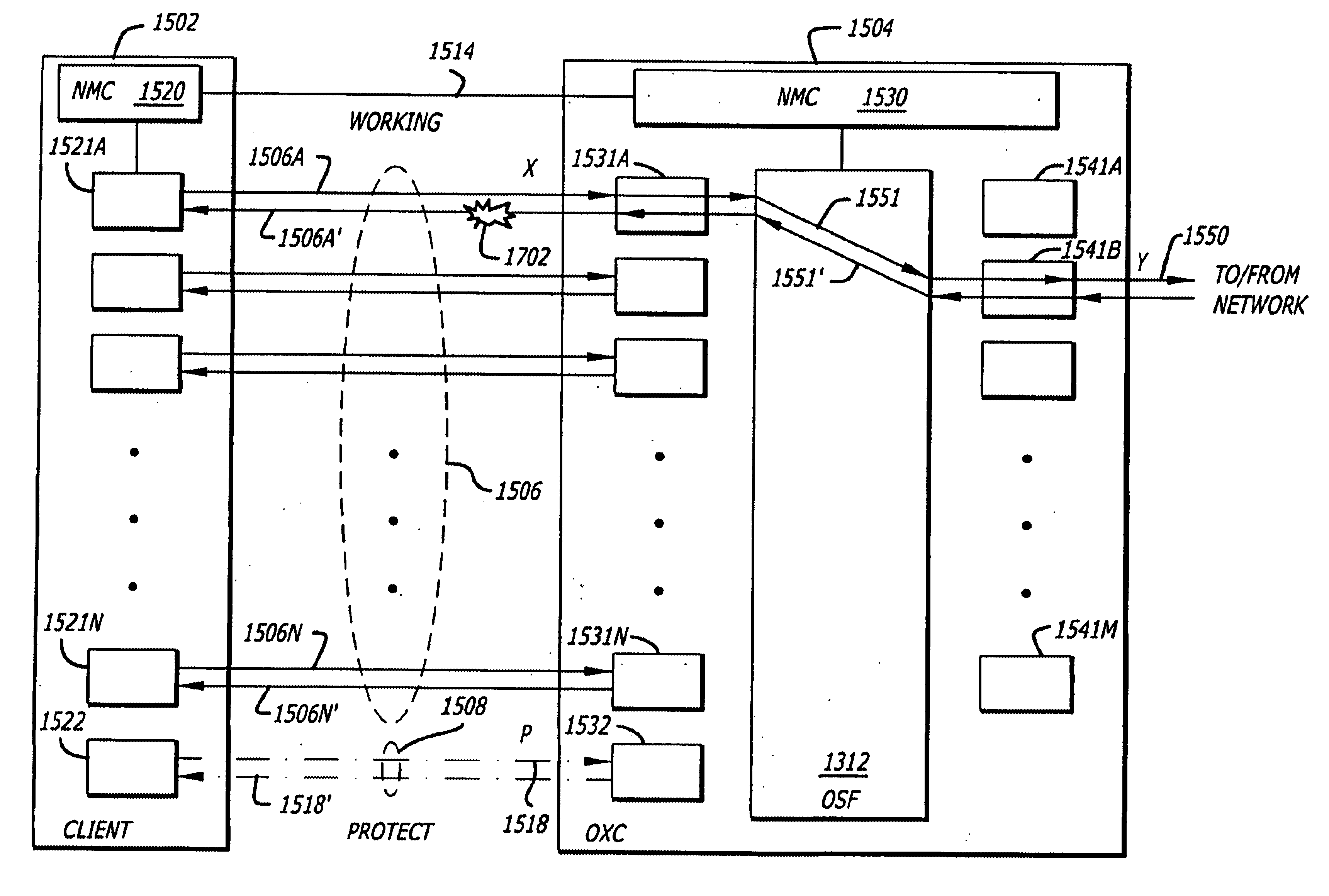
[0035]Herein, the exemplary embodiments of the present invention relate to a scalable, optical cross-connect switching system. These embodiments are not exclusive; rather, they merely provide a thorough understanding of the present invention. Well-known circuits are not set forth in detail in order to avoid unnecessarily obscuring the present invention.

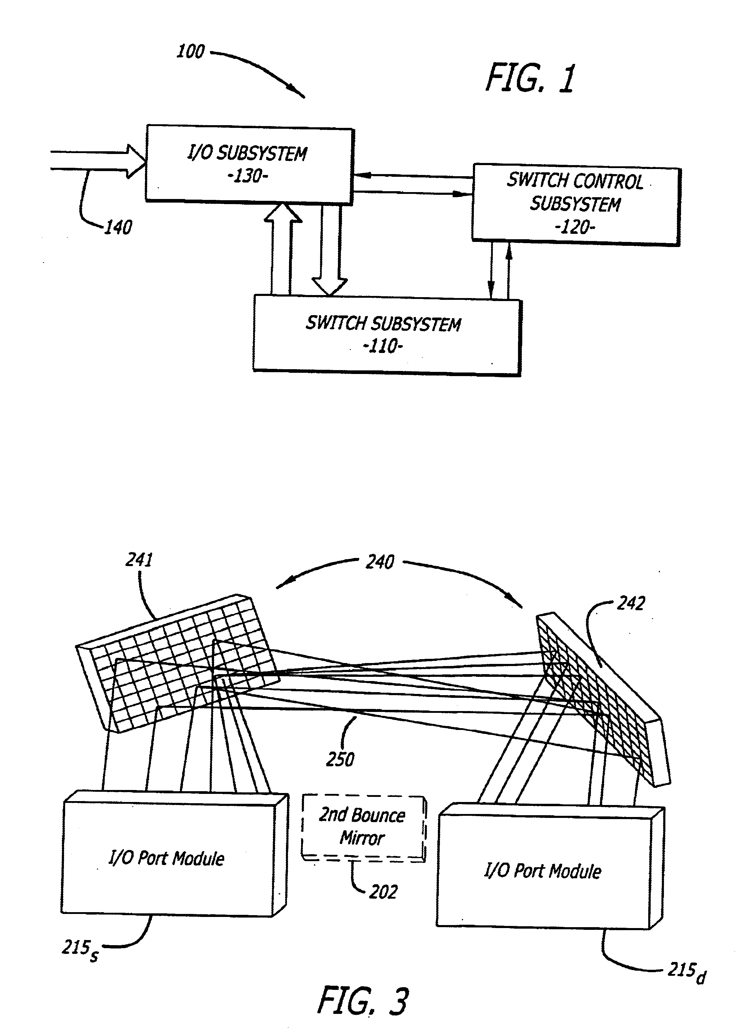
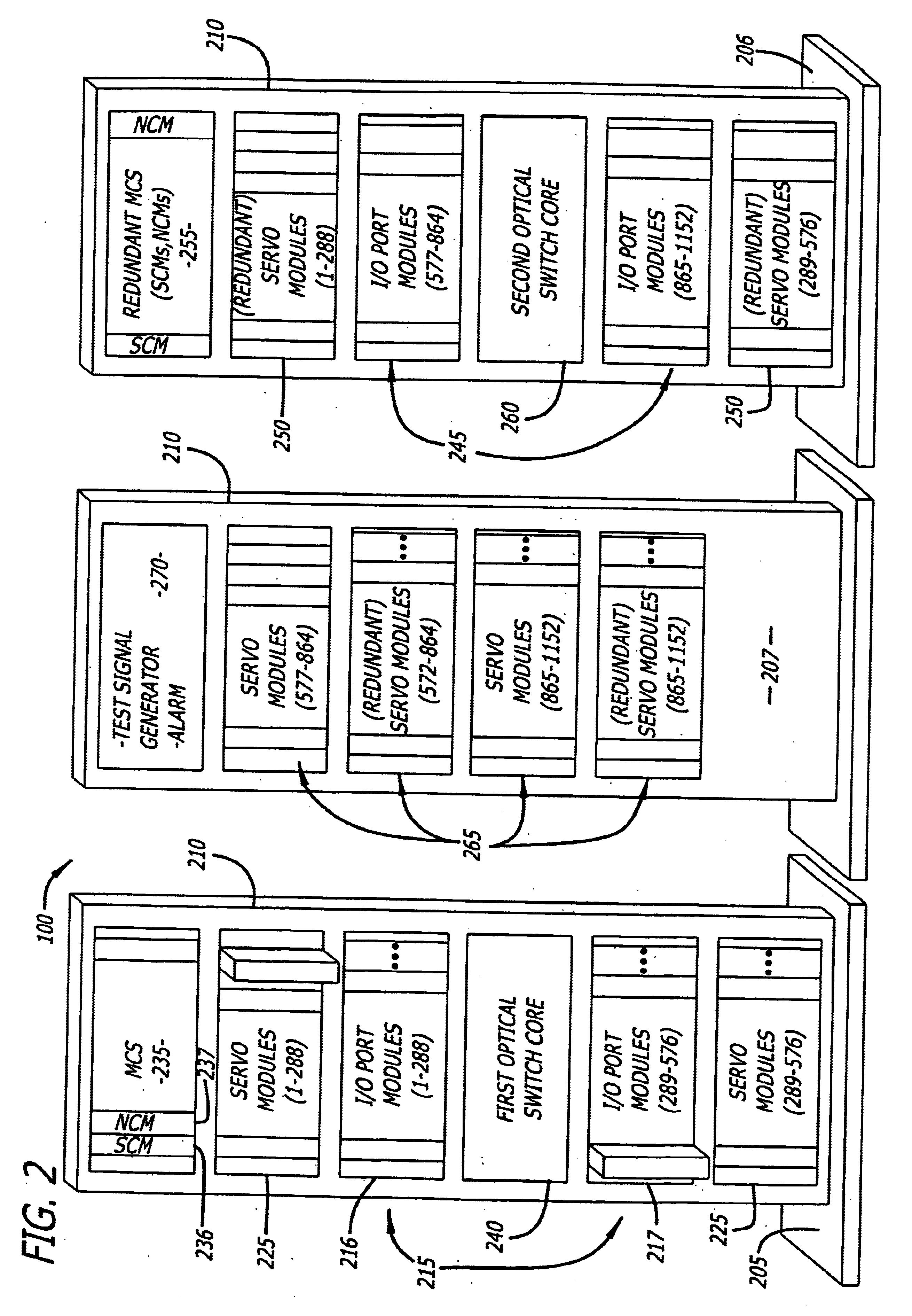
[0036]In the following description, certain terminology is used to describe various features of the present invention. For example, a “module” includes a substrate normally formed with any type of material or materials upon which components can be attached such as a printed circuit board or a daughter card for example. Examples of a “component” include an optical switch, a processing unit (e.g., Field Programmable Gate Array “FPGA”, digital signal processor, general microprocessor, application specific integrated circuit “ASIC”, etc.), couplers and the like. A “coupler” is a component that performs a bridging operation on an input lig...


PUM


Abstract

The present invention provides methods, apparatus and systems for protecting connections between optical cross-connect switches and client equipment. A connection failure is detected, signaled, and a switch made by the client equipment and the optical cross-connect switch to a protection connection between them so as to minimize service interruption. An out-of-band channel or an in-band channel can be used to signal the connection failure.

Description

CROSS REFERENCE TO RELATED APPLICATIONS[0001]This non-provisional U.S. Patent Application claims the benefit of U.S. Provisional Patent Application No. 60 / 162,936 entitled “OPTICAL CROSSCONNECT WITH OPTICAL TO ELECTRICAL CONVERTERS” filed on Nov. 2, 1999 by inventor Rajiv Ramaswami; and also claims the benefit of U.S. Provisional Patent Application No. 60 / 170,094 entitled “OPTICAL CROSSCONNECT WITH BRIDGING, TEST ACCESS AND REDUNDANCY” filed on Dec. 10, 1999 by inventors Rajiv Ramaswami and Robert R. Ward; and also claims the benefit of U.S. Provisional Patent Application No. 60 / 170,095 entitled “OPTICAL CROSSCONNECT WITH LOW-LOSS BRIDGING, TEST ACCESS AND REDUNDANCY” filed on Dec. 10, 1999 by inventors Steven Clark and Rajiv Ramaswami; and also claims the benefit of U.S. Provisional Patent Application No. 60 / 170,093 entitled “1+1 OPTICAL PROTECTION USING OPTICAL CROSSCONNECT” filed on Dec. 10, 1999 by inventors Rajiv Ramaswami and Robert R. Ward; and also claims the benefit of U.S....

Claims


Application Information

Patent Timeline
Patent Type & Authority Patents(United States)
IPC IPC(8): H04J14/02H04Q11/00G02B6/43
CPCH04J14/0241H04J14/0293H04Q11/0062H04J14/0227G02B6/43H04J14/0283H04J14/0297H04Q2011/0024H04Q2011/0026H04Q2011/0041H04Q2011/0043H04Q2011/005H04Q2011/0073H04Q2011/0081H04Q2011/0083
Inventor ERICKSON, KENTKALIGOTIA, SUBHASHINIRAMASWAMI, RAJIV
Owner NORTEL NETWORKS LTD
Why Eureka
Try Eureka