Fiber profile for achieving very high dispersion slope

a fiber profile and optical waveguide technology, applied in the field of fiber profiles for achieving very high dispersion slope, can solve the problems of difficult design of dcf to compensate for the low value of a leaf, degrading the optical signal transmission of nonlinear optical effects, and the lack of acceptance of dual fiber dispersion compensation to date, so as to achieve full dispersion and dispersion slope compensation, and high negative dispersion , the effect of increasing the flexibility of choosing such

Inactive Publication Date: 2005-04-19
CORNING INC
View PDF7 Cites 2 Cited by
  • Summary
  • Abstract
  • Description
  • Claims
  • Application Information

AI Technical Summary

Benefits of technology

[0009]An advantage can be achieved for compensating low K value transmission fibers, such as LEAF, by dual fiber compensation including a fiber with high negative dispersion. Decoupling dispersion slope compensation and dispersion compensation into separate fibers provides a much greater flexibility in choosing such fibers for a par

Problems solved by technology

In long-haul optical networks, nonlinear optical effects can degrade the optical signal transmission.
It has been difficult to design a DCF to compensate for the low κ value of a LEAF.
Each of these solutions has prob

Method used


Image

  • Fiber profile for achieving very high dispersion slope
  • Fiber profile for achieving very high dispersion slope
  • Fiber profile for achieving very high dispersion slope

Examples


example 1

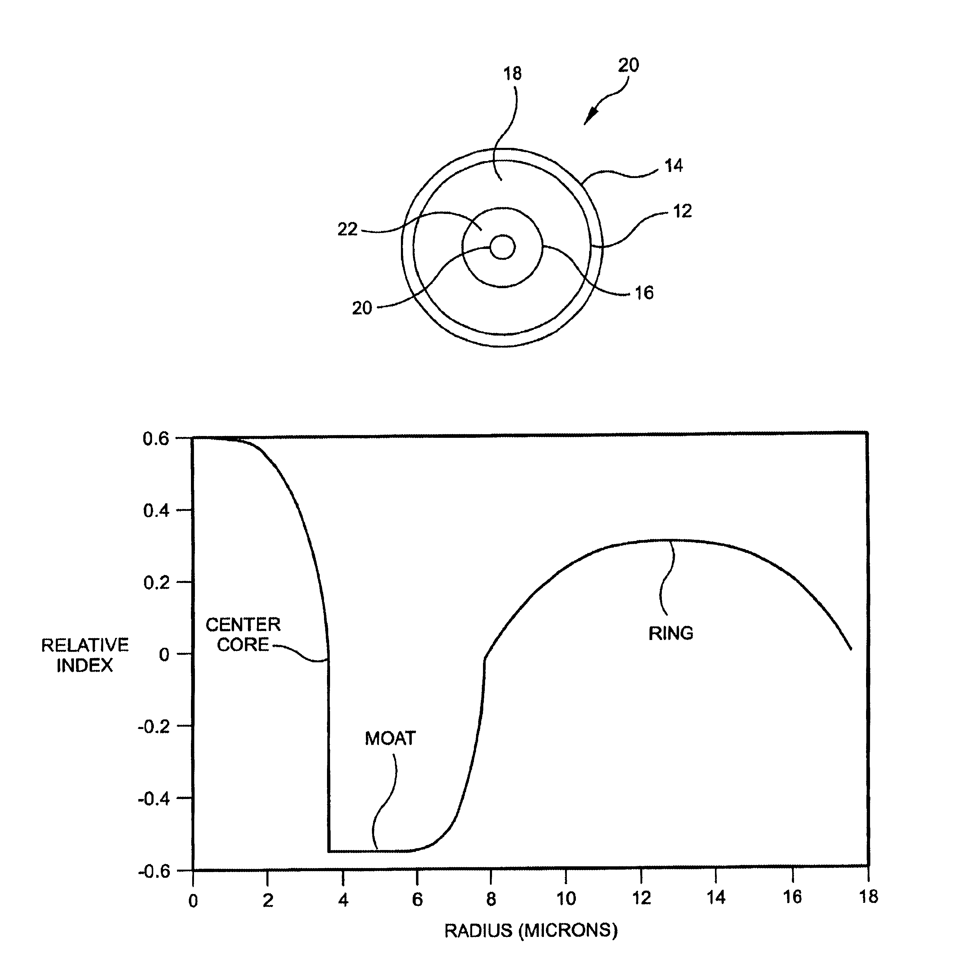
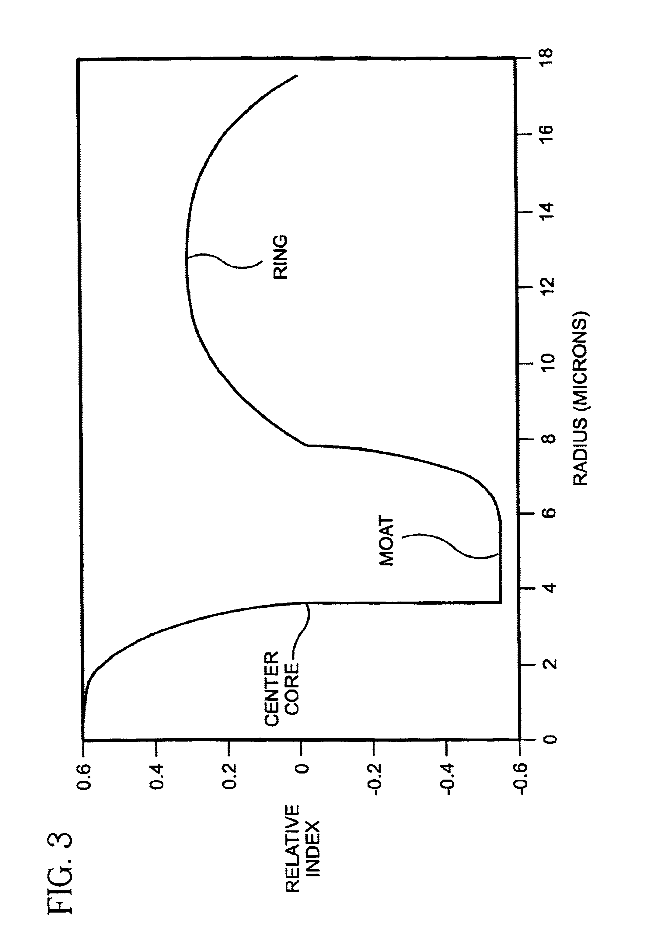
[0041]FIG. 3 is a relative index profile of the core region for Example 1 of the present invention according to the second embodiment of the high negative dispersion slope waveguide. In Example 1, the central segment, moat segment and ring segment outer radii are about 4, 8 and 18 microns, respectively. In this first example, the relative indices of the central segment Δc%, moat segment Δm% and ring segment ΔT% are about 0.6%, −0.55% and 0.3%, respectively.

example 2

[0042]FIG. 4 shows the relative index profile of the core region for Example 2. In Example 2, the central segment, moat segment and ring segment outer radii are about 4, 10 and 14 microns, respectively. In this second example, the relative indices of the central segment Δc%, moat segment Δm% and ring segment ΔT% are about 0.6%, −0.55% and 0.4%, respectively.

example 3

[0043]FIG. 5 shows the relative index profile of the core region for Example 3. In Example 3, the central segment, moat segment and ring segment outer radii are about 4, 9 and 22 microns, respectively. In this third example, the relative indices of the central segment Δc%, moat segment Δm% and ring segment ΔT% are about 0.6%, −0.55% and 0.3%, respectively.

[0044]Table I lists the dispersion, dispersion slope, effective area, and wavelength cutoff for the relative index profiles of the waveguides in Examples 1 to 3.

[0045]

TABLE IDispersionDispersion slopeEffective areaCutoffProfile(ps / nm−km)(ps / nm2−km)(microns2)(microns)Exp. 1−126−1143.94.57Exp. 2−82−543.73.03Exp. 3−165−25.5547.835.02

[0046]As table 1 illustrates, the wavelength cutoff remains above 3 microns for all three examples. For typical fiber transmission applications, the transmission wavelength range is between approximately 1450 nm (1.45 microns) and 1700 nm (1.7 microns). Thus, for typical transmission applications, all thre...


PUM


Abstract

A dispersion slope compensating optical waveguide, such as a fiber, having a high negative dispersion slope is provided. The optical waveguide comprises a core region and an clad layer. The core region further comprises a first region and a second region surrounding the first region. The width of the second region is sufficient to confine electromagnetic radiation within a selected wavelength range to substantially only the core region. Thus, bending loss in the waveguide is substantially reduced. The negative dispersion slope of the dispersion slope compensating optical waveguide can be used in conjunction with a dispersion compensating optical waveguide as a dual optical waveguide to compensate both the dispersion and dispersion slope of a transmission waveguide. An optical span and an optical transmission system incorporating the dual optical waveguide is also provided.

Description

PRIORITY DOCUMENT[0001]This application claims the benefit of and priority to U.S. Provisional Patent Application No. 60 / 254,908, filed Dec. 12, 2000.FIELD OF INVENTION[0002]This invention relates to a dispersion slope compensating optical waveguide having a high negative dispersion slope. This invention also relates to a dual optical waveguide, optical waveguide span, and optical transmission system incorporating the dispersion slope compensating optical waveguide.BACKGROUND OF THE INVENTION[0003]In long-haul optical networks, nonlinear optical effects can degrade the optical signal transmission. Such nonlinear optical effects include four-wave mixing (FWM) and Cross-Phase Modulation (XPM). Introducing dispersion in an optical fiber can reduce such nonlinear effects.[0004]The dispersion product or accumulated dispersion of a span of fiber is a measure of the dispersion accumulated over the span. The dispersion product for a fiber of length L with a dispersion D is the product of L ...

Claims


Application Information

Patent Timeline
IPC IPC(8): G02B6/028G02B6/02H04B10/18
CPCG02B6/02009G02B6/02223G02B6/02261H04B10/25253G02B6/0286G02B6/03644G02B6/0228
Inventor SRIKANT, VAIDYANATHAN
Owner CORNING INC
Why Eureka
Try Eureka