Impeller for rotary slicing machine

a rotary slicing machine and slicing blade technology, which is applied in the direction of blade accessories, machines/engines, waterborne vessels, etc., can solve the problems of small percentage of french fries with thin fries, tapered and other undesirable cuts, disorientation and potential bruising, etc., to prevent disorientation of food products, improve the alignment of food products, and not easily dislodged

Inactive Publication Date: 2005-04-26
URSCHEL LAB
View PDF18 Cites 33 Cited by
  • Summary
  • Abstract
  • Description
  • Claims
  • Application Information

AI Technical Summary

Benefits of technology

[0016]The orientation of the paddles with respect to the base plate and ring of the impeller of the present invention improves the alignment of food products in conjunction with the centrifugal forces generated on the food products during rotation of the impeller so that the food products are more securely positioned and held when they come into contact with the slicing blade so they do not dislodge easily. Additionally, the orientation of the paddles urges the centrifugal forces to index the food products toward the base during rotation so as to align the food products with the slicing blade, thus providing an indexing action on the food products with respect to the slicing blade and the circular blades of the slicing machine. Furthermore, the orientation of the paddles protects the food products from colliding with other food products entering the impeller so as to prevent disorientation of food products already carried by the impeller.

Problems solved by technology

Although the conventional impeller generally works well, under certain circumstances, depending upon the raw potato size, slice thickness and other variables, it has been found that a small percentage of french fries have thin, tapered and other undesirable cuts.
Another reason is that there is a tendency for some potatoes to bounce off of the paddles upon entry into the impeller, resulting in misalignment with respect to the paddles.
Furthermore, as potatoes are fed into the impeller, there is a probability that potatoes may collide with one another, resulting in disorientation and potential bruising.
As a result of the slower advancement and rotation of the smaller portion, there is potential for the smaller potato portions to be cut in subsequent slicing operations which may result in short, tapered and thin cuts of undesirable proportions.
However, this solution serves primarily to orient a potato in a desired orientation and does not register a potato from one end with respect to the impeller.
One major drawback with this impeller is the fact that due to the shape of the impeller blades, a large amount of spaced is required for the impeller.
As a consequence, the housing of the rotary slicing machine must be designed accordingly, and thus existing rotary slicing machines are precluded from using such an impeller.
However, this type of impeller does not sufficiently cooperate with centrifugal forces present during the rotation of the impeller so as to urge a potato axially against the forward ring 10 or the base plate 12 to thereby index the potato to enable consistent slices to be made from the potato.

Method used


Image

  • Impeller for rotary slicing machine
  • Impeller for rotary slicing machine
  • Impeller for rotary slicing machine

Examples


Embodiment Construction

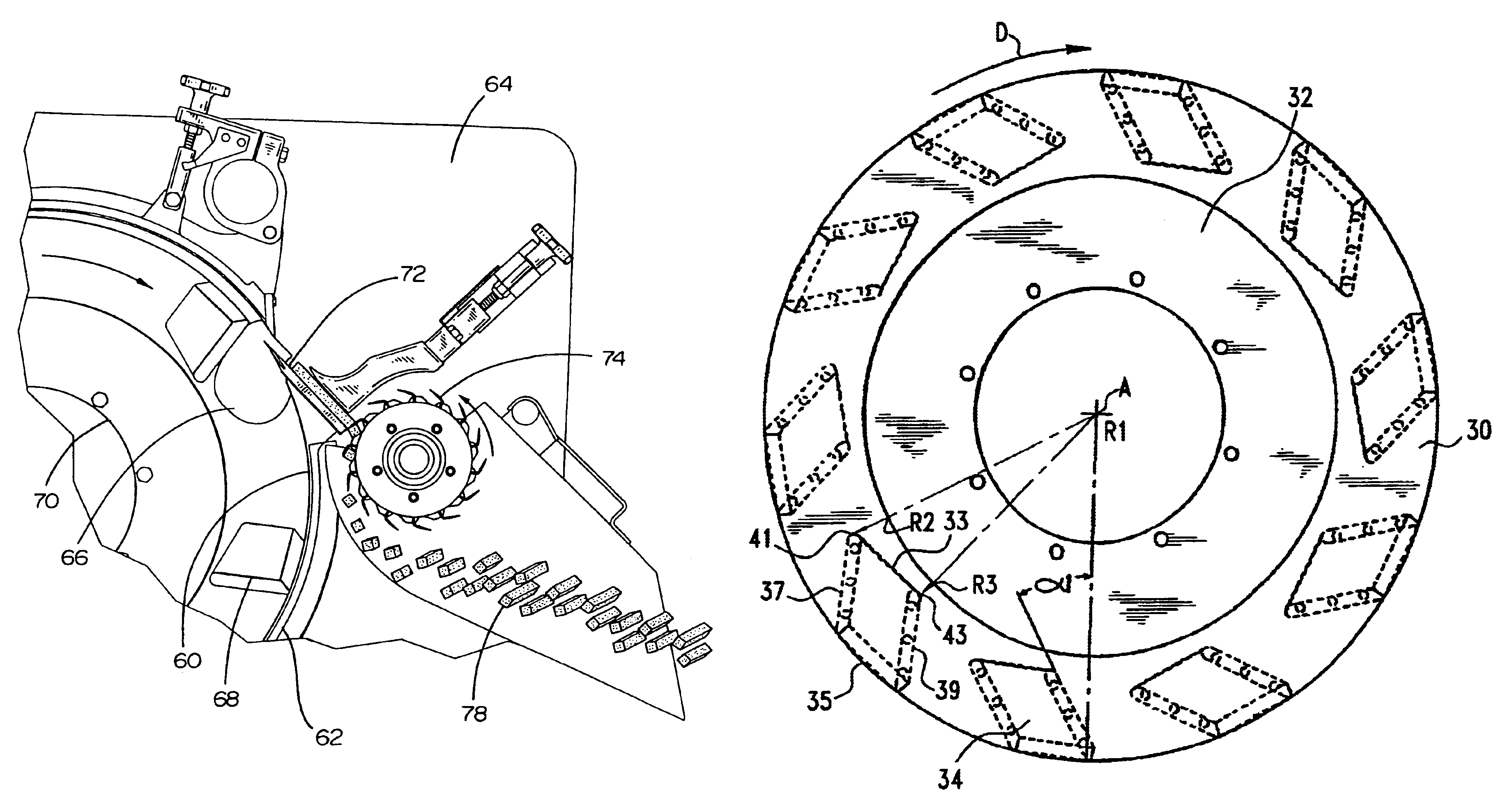
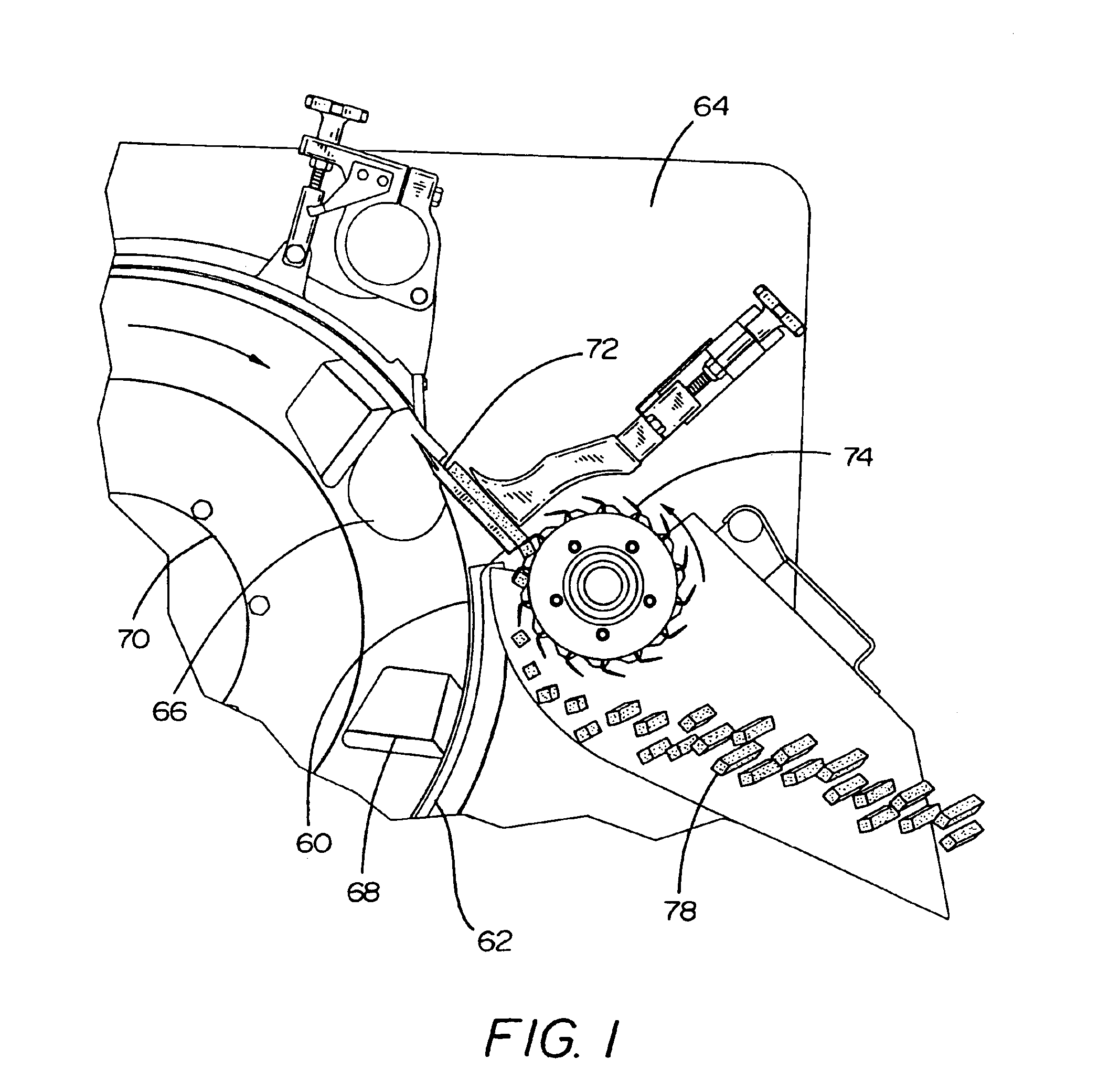
[0033]As illustrated in FIG. 1, a rotary slicing machine includes an open ended, impeller 70 that is mounted for rotation in a non-rotating drum 62 formed by a stationary housing 64 of the machine. The impeller 70 is rotatably driven about an axis coincident with the cylindrical axis of the drum to centrifugally throw the food products 66 in a radially outward direction. Since the slicing operation is continuous, the impeller paddles 68 are constantly moving in a circular path about the interior surface 60 of the drum. The centrifugal force holds the food products 66 against the interior surface 60 of the drum as the impeller rotates so as to carry the food products 66 past a slicing blade 72 to cut the food products into slab-like slices. The slices are immediately guided into a cross-cut assembly 74 where they are cut into strips 78.

[0034]An embodiment of the impeller of the present invention is shown in FIGS. 5-7. The impeller includes a circular rear base plate 32 and at least o...


PUM

PropertyMeasurementUnit
angleaaaaaaaaaa
angleaaaaaaaaaa
constant angleaaaaaaaaaa

Abstract

An improved impeller for use in a rotary food slicing machine comprising a rear base plate and at least one forward ring secured in axial spaced parallel relation relative to the rear base plate and a plurality of circumferentially spaced planar paddles spanning the base plate and the forward ring. The paddles are each oriented to extend at an angle relative to the radius of the rear base plate and the at least one forward ring. Moreover, the end of each paddle located adjacent to the rear base plate is arranged in a partially trailing relationship relative to the end of the paddle located adjacent the at least one forward ring with respect to the intended direction of rotation of the impeller.

Description

BACKGROUND OF THE INVENTION[0001]This invention generally relates to an impeller for a rotary slicing machine for cutting food products and the like into slices. More particularly, this invention relates to an impeller for a rotary slicing machine, wherein the impeller has angled paddles that are arranged to transport, align and centrifugally throw out a food product in a radial direction within a drum type slicing machine so as to be cut by a fixed slicing blade mounted adjacent to the path of motion of the impeller and food product.[0002]Food slicing machines of various types are used to cut, slice, dice and otherwise reduce the size of larger food products into smaller pieces depending upon the configuration of various knives carried by the machine. One type of a food slicing machine is a rotary slicing machine such as shown in U.S. Pat. No. 3,521,688, granted Jul. 28, 1970 to Urschel et al.[0003]A conventional rotary slicing machine includes an open ended, generally annular impe...

Claims


Application Information

Patent Timeline
Patent Type & Authority Patents(United States)
IPC IPC(8): B26D1/36B26D1/01B26D3/22
CPCB26D1/02B26D7/0691B26D3/22B26D1/36Y10T83/4795Y10T83/6473Y10T83/6476Y10T83/6489Y10T83/9372
Inventor ARRASMITH, PAUL E.BUCKS, BRENT L.
Owner URSCHEL LAB
Why Eureka
Try Eureka