Seating for amphibious vehicles

a technology for amphibious vehicles and seats, which is applied in the direction of floating buildings, crew accommodation, vessel construction, etc., can solve the problems of corrosion and/or jamming of the seat on the track, water splashing into, and sand blowing into the vehicl

Inactive Publication Date: 2005-04-26
LIPSCOMBE GEOFFREY
View PDF5 Cites 9 Cited by
  • Summary
  • Abstract
  • Description
  • Claims
  • Application Information

AI Technical Summary

Benefits of technology

[0007]The object of the invention is to provide an arrangement for support of a seat sufficiently far above the floor of an amphibious vehicle to avoid the above problems; and to enable the driver to sit above the road seating position so as to assist steering when on water.
[0009]Such an arrangement according to the invention ensures that the seat adjustment mechanism is above the dirt and slop level, and reduces the likelihood of jamming caused either by corrosion; or by the build-up of material in and around tight fitting parts. The arrangement also enables the driver to assume an elevated single position when on water. Furthermore, seat mountings according to the invention have a lower ratio of cushion height to mounting width than prior art amphibious vehicle seats, allowing provision of a more stable seat mounting with greater resistance to wear in service.
[0010]The co-operating parts of the seal adjustment mechanism may be a slide and a rail; or a roller or rollers and a rail. These parts may be mounted so that the rail is fixed in relation to the floor of the vehicle, or so that the rail is fixed to the seat. The co-operating parts are preferably mounted well above the floor, and in one embodiment of the invention the inter-engagement between the co-operating parts is at a level at about the same as the top of the seat cushion, the seat cushion being distinct from the backrest. At this latter level, a latch for fixing the seat adjustment is more convenient than at a level below the seat, as is normal with known arrangements. Furthermore, electrically operated seat adjustment can be kept well away from water and slops. The rails may face upwards, downwards or sideways depending on the room available for mounting on either side of the seat. Where the rails are mounted facing sideways, the seat may have flexible splash guards fixed to the seat above the rails on either side of the seat to further guard the track.

Problems solved by technology

A problem with amphibious vehicles is that when they are open topped, water splashes into the vehicle and may slop around on the floor; and sand may also blow into the vehicle.
The combination of sand and water in and around the seat track may well cause corrosion and / or jamming of the seat on its track.
A further problem is that steering an amphibious vehicle in its marine mode requires the driver to sit higher than the position best suited for road use.
The seats may oscillate as the occupants shift from side to side according to the movement of the vehicle, causing the occupants to feel insecure.
The high bending moments applied to seat and mounting components may also cause rapid wear.
The issue of perceived seat stability is particularly germane to a centre mounted seat, as there is no practical possibility in this case of the occupant restraining himself or herself against the vehicle interior trim on door, side panel, or centre console, should the seat mounting be considered to have lateral movement beyond the occupant's envelope of comfort and security.

Method used


Image

  • Seating for amphibious vehicles
  • Seating for amphibious vehicles
  • Seating for amphibious vehicles

Examples


Embodiment Construction

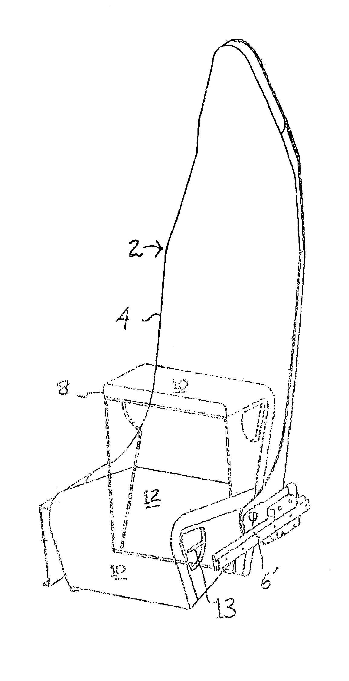
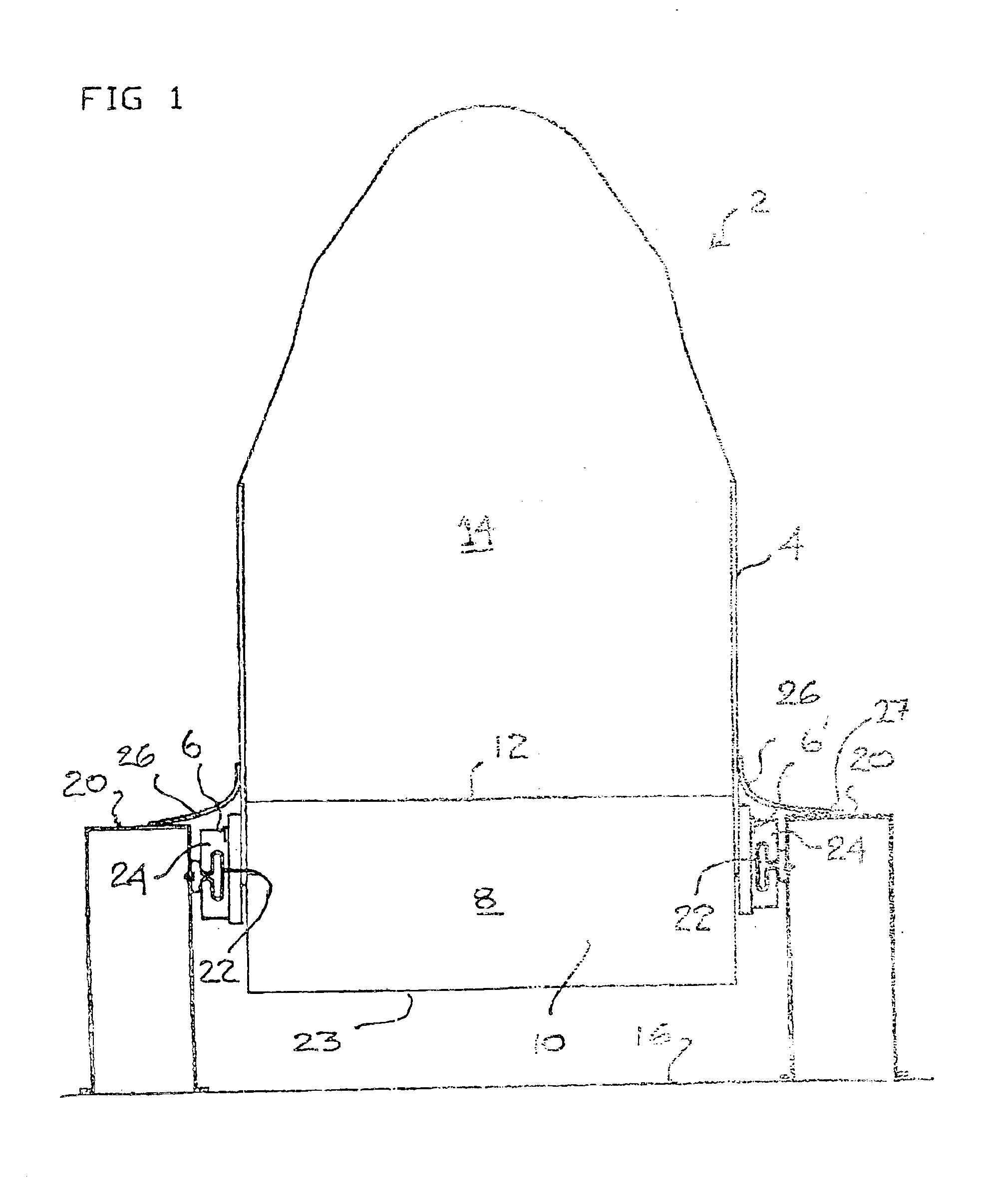
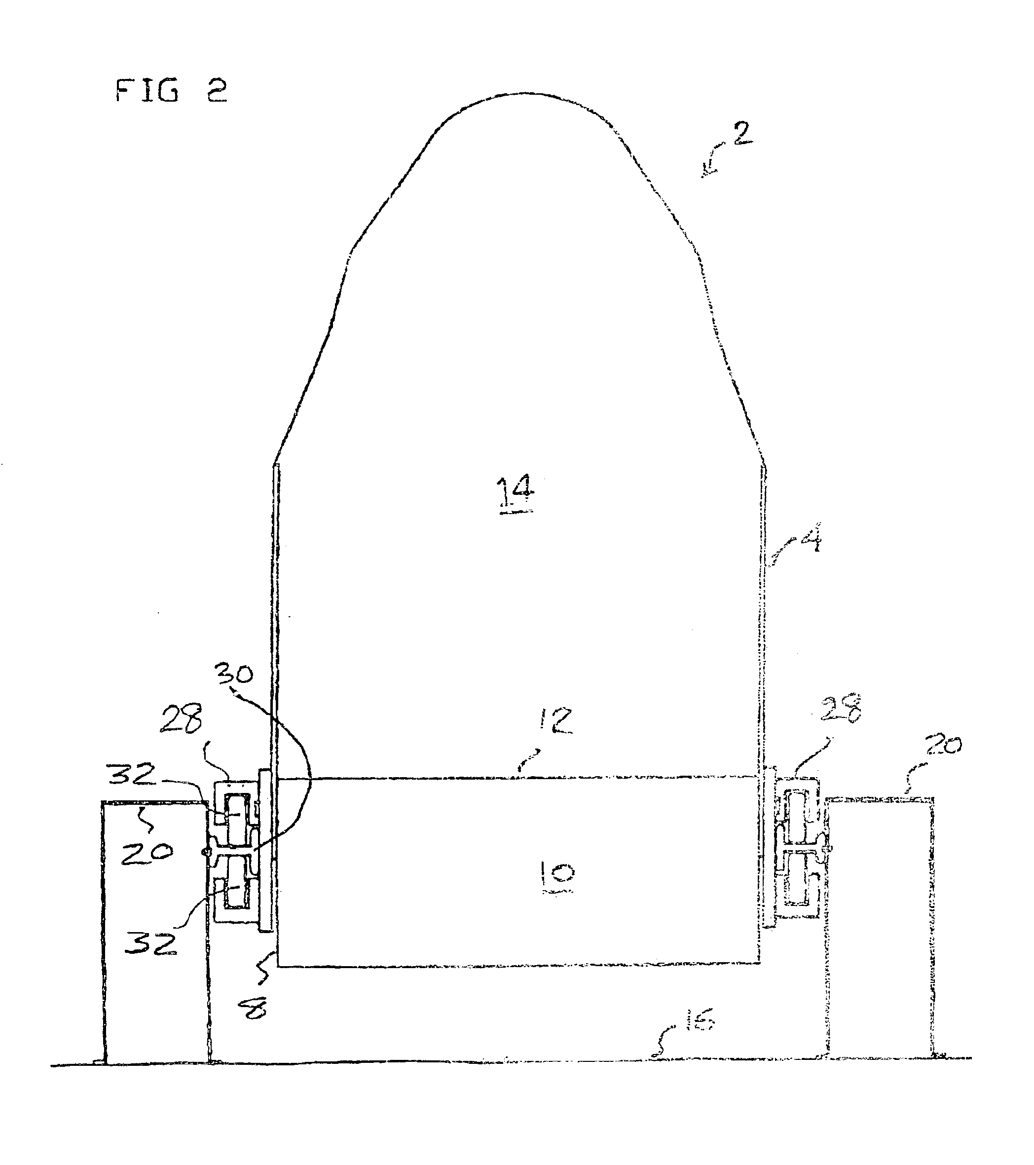
[0021]FIG. 1 shows a seat generally at 2 having a frame 4. A tip-up seat cushion 8 is pivotally mounted at pivots 6 and 6′—see also FIGS. 5, 7, and 8 for similar seats. In FIGS. 7 and 8 the tip-up seat 8 is shown in the down / road driving position in said lines: whilst the seat 8 is shown in the up / water driving position in broken lines. The seat 8 has a locking handle 13 on one side, which operates as shown in FIG. 5. Handle 13 actuates pin or bar 15, shown in broken lines; which in turn engages one of two notches 17, 17′ in circular plate 19 on the pivot axis 6-6′, to hold tip-up seat 8 in one position or the other.

[0022]The driver or helmsman sits on the tip-up cushioned seating area 10 when the seat is in the up, or water, position; and on seat cushion 12 when the seat is in the down, or road, position. Numeral 14 denotes the backrest.

[0023]A further locking handle 18 is provided on the other side of seat 2 to handle 13. This further handle is used to lock the fore-and-aft adjust...


PUM


Abstract

Seat 2 is mounted to slide blocks 24 and rails 22, which in turn are mounted to upstanding brackets 20. The fore-and-aft adjustment of the seats is thus raised above the level of floor 16, avoiding fouling by sand and dirt; corrosion; and shorting where electric seat adjustment is used. Seat 2 comprises frame 4, backrest 14, and tip-up seat 8 which can be raised around pivots 6, 6′ to allow a higher seating position for marine use. In marine mode, the helmsman sits on cushion 10; in road mode, the driver sits on cushion 12. Latches are provided for fore-and-aft and tip-up cushion adjustment. Flaps 26 may protect sliding surfaces from contamination. Rails 22 may face upwards (34, FIG. 3), downwards (44, FIG. 4), or sideways, as convenient; the seat may be supported on a cradle (40, FIG. 4). Slide blocks may be replaced by rollers (32, FIGS. 2, 6).

Description

CROSS REFERENCE TO RELATED APPLICATIONS[0001]The present application claims priority from GB Patent Application Serial No. 02186047, filed Aug. 10, 2002.[0002]The present invention relates to an amphibious vehicle having a seat adjustable in a fore and aft direction relative to a floor of the vehicle.BACKGROUND OF THE INVENTION[0003]Amphibious vehicles normally have at least the driver's seat adjustably mounted to the floor of the vehicle by means of a track comprising a pair of rails attached directly to the floor. The seat engages with the track by means of rollers and a latch is provided to hold the seat at a particular position by latching onto the rail. This type of arrangement is also used for normal road vehicles. A problem with amphibious vehicles is that when they are open topped, water splashes into the vehicle and may slop around on the floor; and sand may also blow into the vehicle. The combination of sand and water in and around the seat track may well cause corrosion a...

Claims


Application Information

Patent Timeline
Patent Type & Authority Patents(United States)
IPC IPC(8): B60F3/00B60N2/06B60N2/30B60N2/24B60N2/32B60N2/075B60N2/07B63B29/00B63B29/06
CPCB60F3/003B60N2/071B60N2/0747B60N2/075B60N2/3047B60N2/32B63B29/06B60N2/24B60N2002/247
Inventor LIPSCOMBE, GEOFFREY
Owner LIPSCOMBE GEOFFREY
Why Eureka
Try Eureka