Dust cover receiving structure of hydraulic shock absorber

a technology of hydraulic shock absorber and receiving structure, which is applied in the direction of shock absorbers, wound springs, transportation and packaging, etc., can solve the problems of increasing assembly time, affecting the service life of the shock absorber, and the inability to protect the surface of the spring seat, so as to prevent the dust cover from bowing and reduce the size of the spring seat

Inactive Publication Date: 2005-04-26
SHOWA CORP
View PDF13 Cites 35 Cited by
  • Summary
  • Abstract
  • Description
  • Claims
  • Application Information

AI Technical Summary

Benefits of technology

[0009]An object of the present invention is to protect a surface of a spring seat as well as to prevent a dust cover from bowing while enabling downsizing of a spring seat, in a hydraulic shock absorber in which an end portion of the dust cover is supported by the spring seat.

Problems solved by technology

Thus, a coating of the spring seat rubs out, and it is impossible to protect a surface of the spring seat.
Further, since the cover receiving portion is provided in the spring seat itself, the spring seat becomes large.
However, according to the structure described in Japanese Utility Model No. 2535936, since it is necessary to connect and fix the end portion of the dust cover to the seat rubber in a narrow space between the damper tube and the suspension spring, the assembling time is increased, and the assembling properties are poor.

Method used


Image

  • Dust cover receiving structure of hydraulic shock absorber
  • Dust cover receiving structure of hydraulic shock absorber
  • Dust cover receiving structure of hydraulic shock absorber

Examples


Embodiment Construction

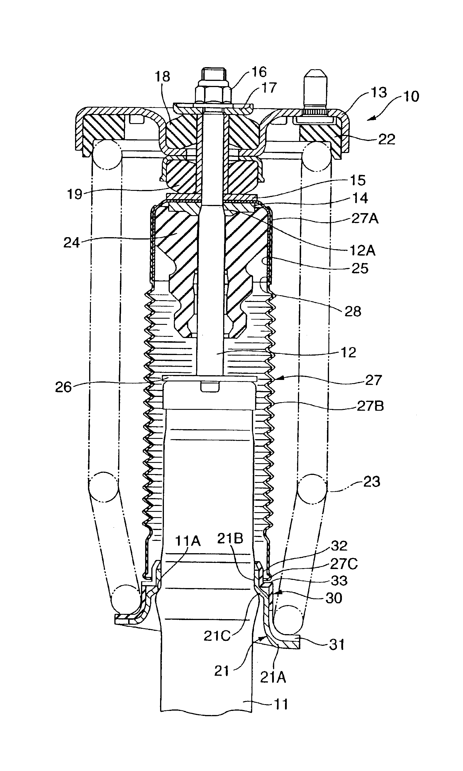
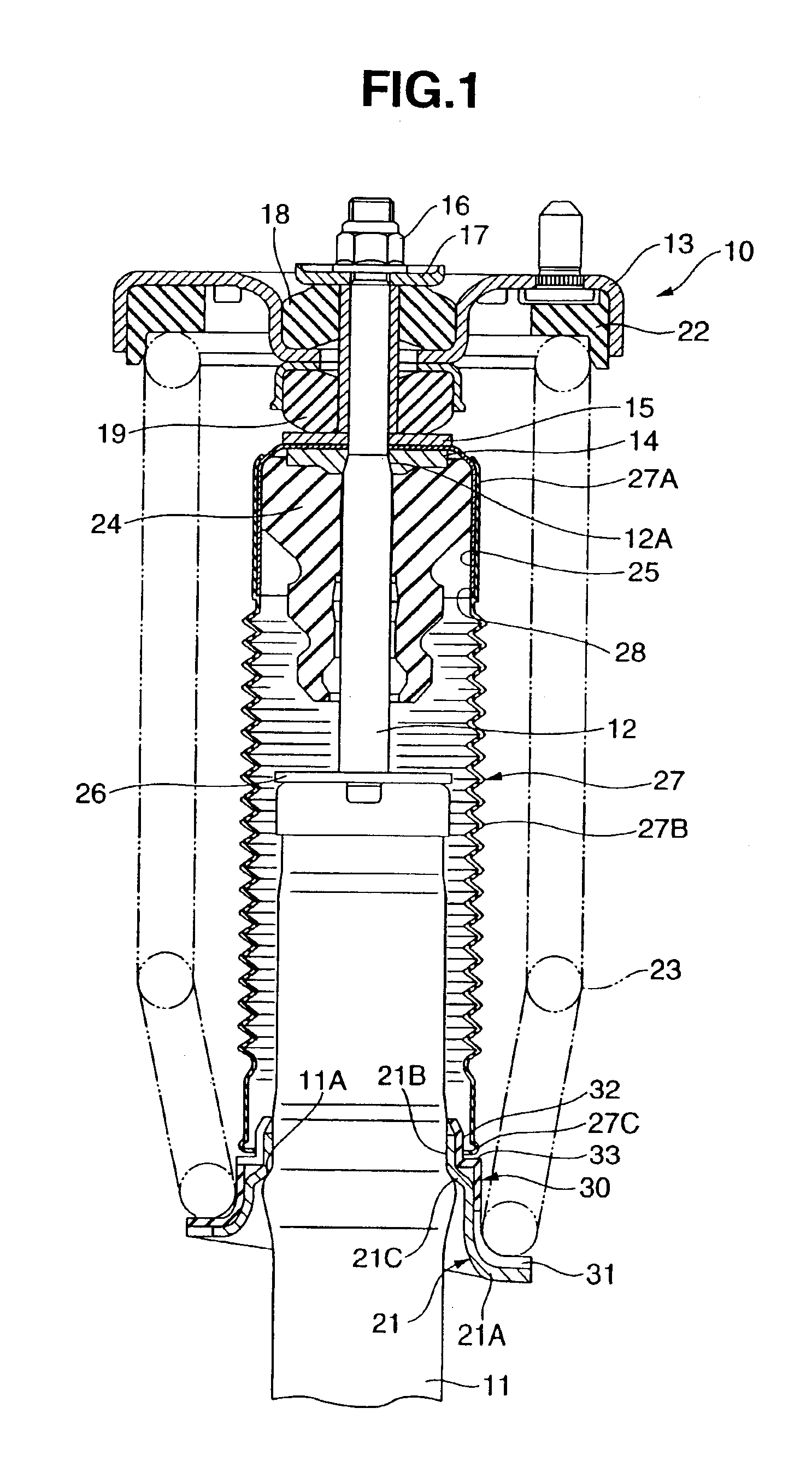
[0017]A hydraulic shock absorber 10 is connected to a tire wheel by inserting a piston rod 12 to a cylinder built in a damper tube 11 and arranging a tire wheel side mounting bracket on the damper tube 11, and is mounted to a vehicle body by arranging a vehicle body side mounting bracket 13 to which is connected the piston rod 12 protruding from the damper tube 11, as shown in FIG. 1. In this case, the vehicle body side mounting bracket 13 is provided in a state in which the vehicle body side mounting bracket 13 is clamped by upper and lower annular rubber mount members (mounts) 18 and 19 between a lower washer 15 supported to a cover plate 14 engaged with a step portion 12A of the piston rod 12, and an upper washer 17 supported to a lock nut 16 engaged with an end portion of the piston rod 12.

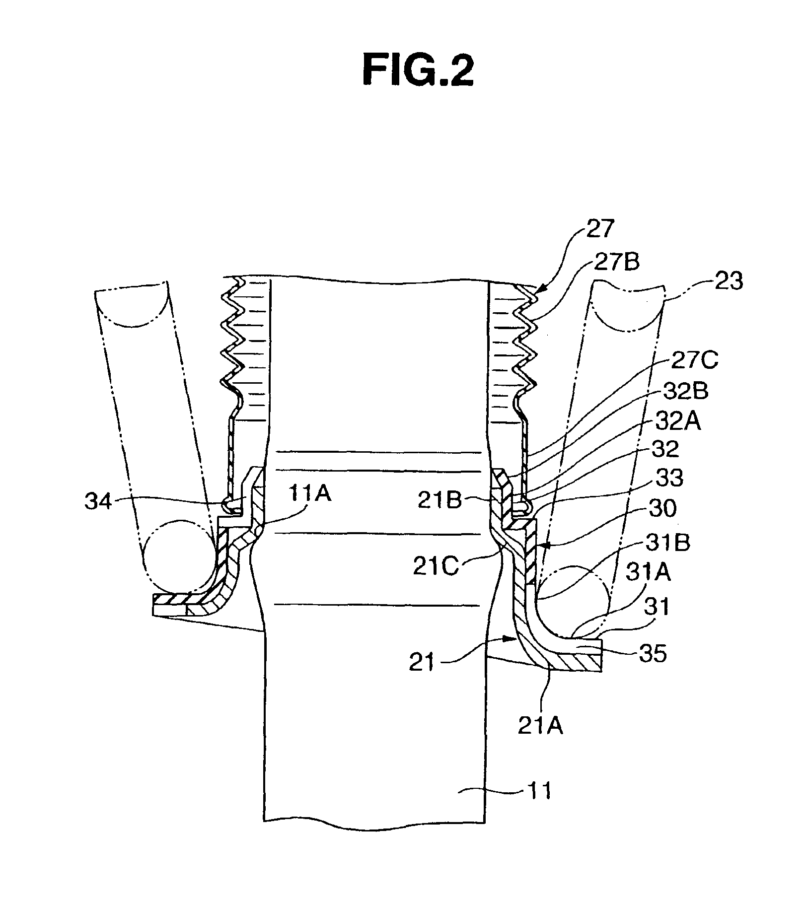
[0018]The hydraulic shock absorber 10 is surrounded by a suspension spring 23 which is arranged between a lower spring seat 21 which is press inserted onto an outer periphery of the damper tub...


PUM


Abstract

A dust cover receiving structure of a hydraulic shock absorber in which a seat rubber is interposed between a suspension spring and a spring seat. The seat rubber has a spring receiving portion which is arranged between the suspension spring and the spring seat, a centering portion which is fitted to a damper tube and guides an end portion of a dust cover in such a manner as to align the dust cover with an axial center of the damper tube, and a cover receiving portion which is provided between the spring receiving portion and the centering portion, and which receives an end surface of the dust cover.

Description

BACKGROUND OF THE INVENTION[0001]1. Field of the Invention[0002]The present invention relates to a dust cover receiving structure of a hydraulic shock absorber.[0003]2. Description of the Related Art[0004]A hydraulic shock absorber having a dust cover which is put on a damper tube and wherein a suspension spring is provided at an outer side of the dust cover, and wherein the dust cover can be supported by a spring seat mounted to the damper tube, is described in Japanese Patent No. 3096006 and Japanese Utility Model No. 2535936.[0005]In the structure described in Japanese Patent No. 3096006, the spring seat is provided with a centering portion which guides an end portion of the dust cover in such a manner as to make the dust cover coaxial with the damper tube, and a cover receiving portion which supports the end surface of the dust cover. The centering portion prevents the dust cover from bowing, and prevents the dust cover from being in contact with the suspension spring and the da...

Claims


Application Information

Patent Timeline
Patent Type & Authority Patents(United States)
IPC IPC(8): B60G15/06B60G11/00B60G13/00B60G11/14B60G15/00F16F1/12F16F9/38F16F1/04F16F9/32
CPCB60G11/14B60G13/003B60G15/063B60G15/068F16F9/38F16F1/126B60G2202/12B60G2204/1242B60G2204/12422B60G2204/45021B60G2202/312
Inventor FUKAYA, YUKIO
Owner SHOWA CORP
Why Eureka
Try Eureka