
High frequency ultrasonic nebulizer for hot liquids

Inactive Publication Date: 2005-04-26
ARCHIMEDES OPERATING
View PDF12 Cites 54 Cited by
  • Summary
  • Abstract
  • Description
  • Claims
  • Application Information

AI Technical Summary

Benefits of technology

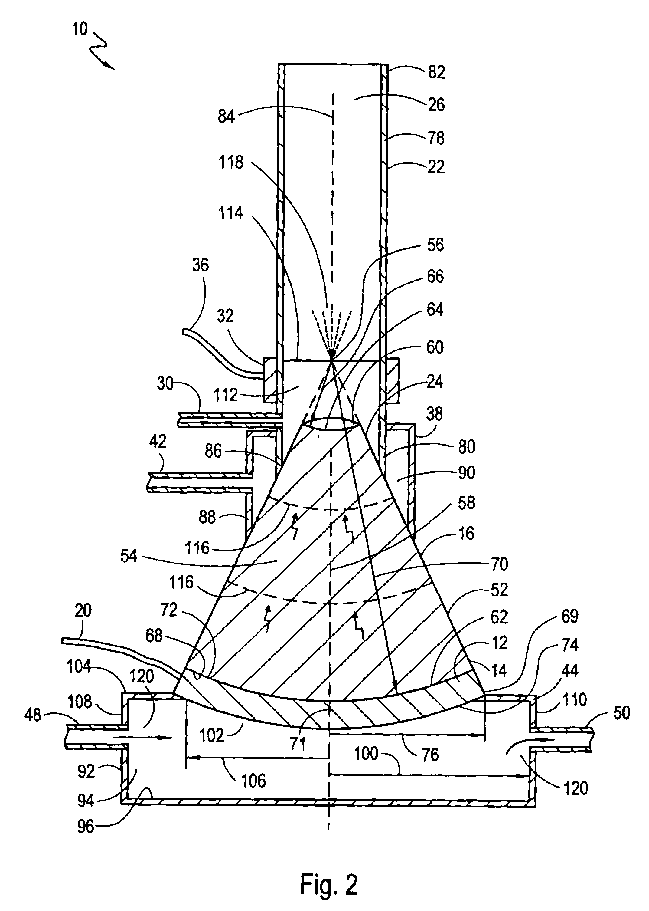
[0015]Preferably, during operation of the system, the pressure vessel maintains an overpressure at the interface to reinforce the fluid-tight seal, and the heater maintains the temperature of the liquid in the liquid chamber above three hundred degrees Centigrade (300° C.). Regardless of the temperature of the liquid in the liquid chamber, the temperature of the piezoelectric transducer is preferably maintained below one hundred degrees Centigrade (100° C.). To accomplish this, the concentrator effectively distances the transducer from direct contact with the liquid chamber. Also, the fluid pump circulates a fluid through the channel of the cooling drum to absorb heat from the piezoelectric transducer and maintain the piezoelectric transducer within its operational temperature range.

Problems solved by technology

Piezoelectric transducers, however, have limited operational temperature ranges.
In general, most piezoelectric transducers will not effectively operate above about one hundred degrees Centigrade (100° C.).
However, as discussed above, when high-temperature liquids are to be nebulized, the conductive transfer of heat from the liquid to the transducer can adversely affect the operation of the transducer.
Accordingly, the adverse effect that high temperatures have on piezoelectric materials has effectively limited their use in nebulizers.
A rod nebulizer, however, has a limited operational frequency range that is dependent on the length of the rod.
Furthermore, the higher frequencies that are needed for most applications require shorter rods.
Thus, heat transfer through the rod to the transducer, again, becomes a problem.

Method used


Image

  • High frequency ultrasonic nebulizer for hot liquids
  • High frequency ultrasonic nebulizer for hot liquids
  • High frequency ultrasonic nebulizer for hot liquids

Examples


Embodiment Construction

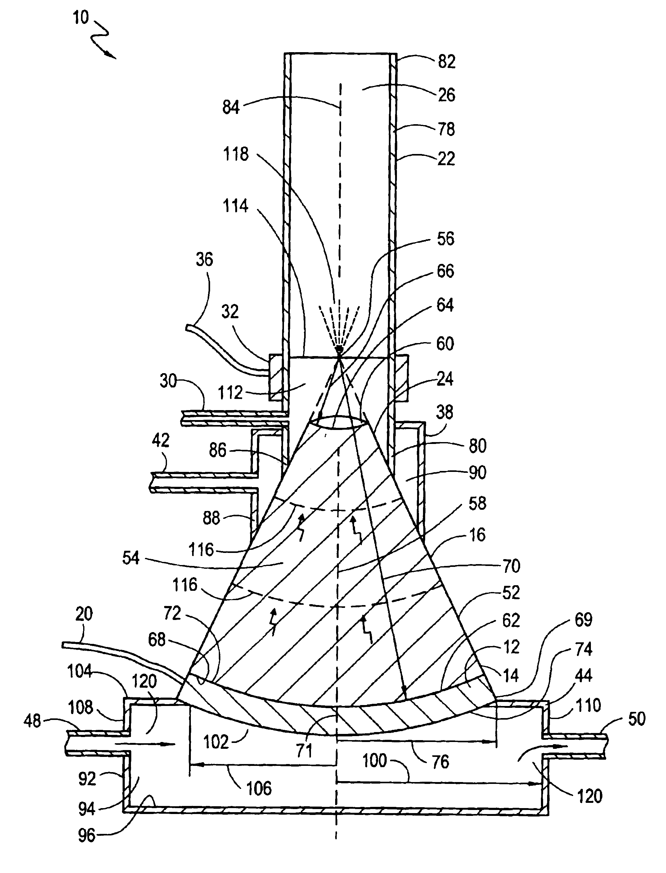
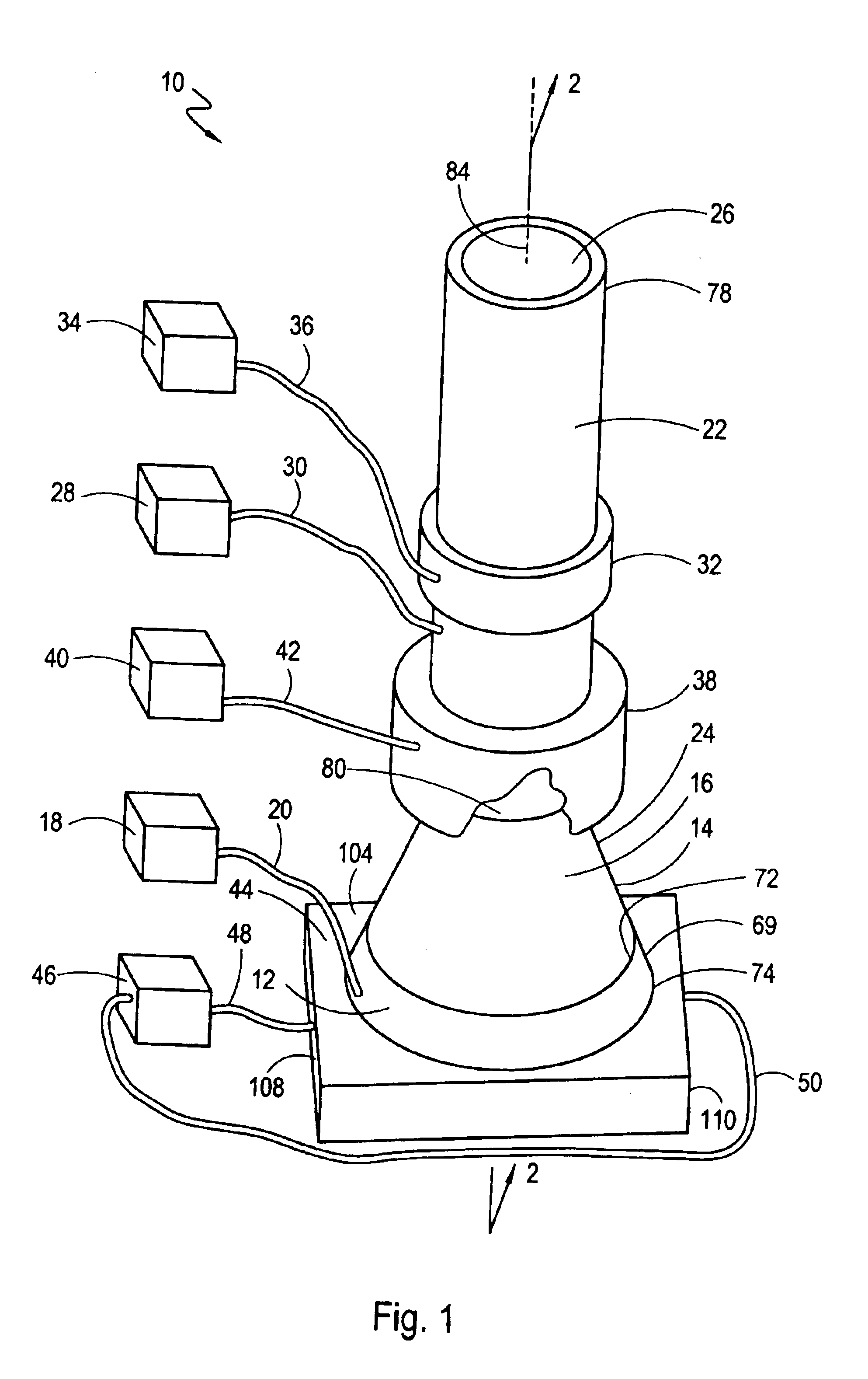
[0019]Referring initially to FIG. 1, a nebulizer system in accordance with the present invention is shown and is generally designated 10. The system 10 includes a transducer 12 that is positioned at the end 14 of a conical concentrator 16. As shown, a power source 18 is connected to the transducer 12 via a power line 20. The system 10 also includes a substantially cylindrical-shaped droplet manifold 22 that is positioned over the end 24 of the conical concentrator 16 to create a liquid chamber 26 inside the manifold 22. Additionally, a high-temperature liquid source 28 is connected to the liquid chamber 26 via a tube 30 to establish fluid communication between the liquid source 28 and the liquid chamber 26.

[0020]The system 10 can also include a heater 32 that is mounted to the manifold 22 to surround the liquid chamber 26. As shown, the heater 32 is connected to a power source 34 via a power line 36. The system 10 can further include a pressure vessel 38 that surrounds at least a po...


PUM

PropertyMeasurementUnit
Temperatureaaaaaaaaaa

Abstract

A nebulizer for atomizing a high-temperature liquid includes a truncated, conical concentrator that defines a vertex and that has a small-diameter end and a large-diameter end. The small-diameter end has a spherical-shaped, concave surface and the large-diameter end has a spherical-shaped, convex surface. A piezoelectric transducer has a spherical-shaped, concave surface that is attached to the convex surface of the concentrator. A cylindrical-shaped droplet manifold is positioned over the small-diameter end of the concentrator to create a liquid chamber in the manifold with the vertex inside the liquid chamber. A feeding tube introduces the high-temperature liquid into the liquid chamber until the surface of the liquid reaches the vertex. With an activation of the transducer, acoustic waves that have spherical wavefronts are launched away from the concave surface of the transducer. The concentrator propagates and directs the spherical wavefronts for convergence at the vertex to nebulize the liquid.

Description

FIELD OF THE INVENTION[0001]The present invention pertains generally to devices and methods for nebulizing liquids. More particularly, the present invention pertains to devices and methods that use acoustic waves for nebulizing liquids. The present invention is particularly, but not exclusively, useful as a device for nebulizing a high-temperature liquid.BACKGROUND OF THE INVENTION[0002]A nebulizer is a device that can be used for converting a liquid into droplets. For some applications, it may be desirable to nebulize a relatively high-temperature liquid (i.e., above 100° C.) into small-diameter droplets (i.e., less than 10 μm). For example, one such application exists in the field of plasma processing. Specifically, in plasma processing, it may be desirable to nebulize a material with a high melting temperature into small-diameter droplets that can then be further heated to create a plasma of the material. Indeed, there are numerous other applications wherein the nebulizing of hig...

Claims


Application Information

Patent Timeline
IPC IPC(8): B05B17/04B05B17/06B22F9/06
CPCB05B17/0615B22F9/06B22F2999/00B22F2202/01
Inventor PUTVINSKI, SERGEIKUTEEV, BORIS V.
Owner ARCHIMEDES OPERATING
Learn More