Sanitary diaphragm valve

a diaphragm valve and diaphragm technology, which is applied in the direction of diaphragm valves, engine diaphragms, operating means/release devices of valves, etc., can solve the problems of early failure of the diaphragm web, and achieve the effect of reducing the stress on the diaphragm and improving the flow ra

Inactive Publication Date: 2005-04-26
SWAGELOK CO
View PDF76 Cites 29 Cited by
  • Summary
  • Abstract
  • Description
  • Claims
  • Application Information

AI Technical Summary

Benefits of technology

[0008]In a further embodiment of the invention, the actuator housing provides support surfaces for the diaphragm that reduces stress on the diaphragm particularly at higher operating pressures.
[0009]In accordance with another aspect of the invention, a deep bowl cavity design is used with a diaphragm that seals radially outside one of the valve ports. This concept gr

Problems solved by technology

However, due to the nature of these substances and the relatively thin flexure sections they form, many corrosive fluids are capable of permeating the flexure section to the surrounding

Method used


Image

  • Sanitary diaphragm valve
  • Sanitary diaphragm valve
  • Sanitary diaphragm valve

Examples


Embodiment Construction

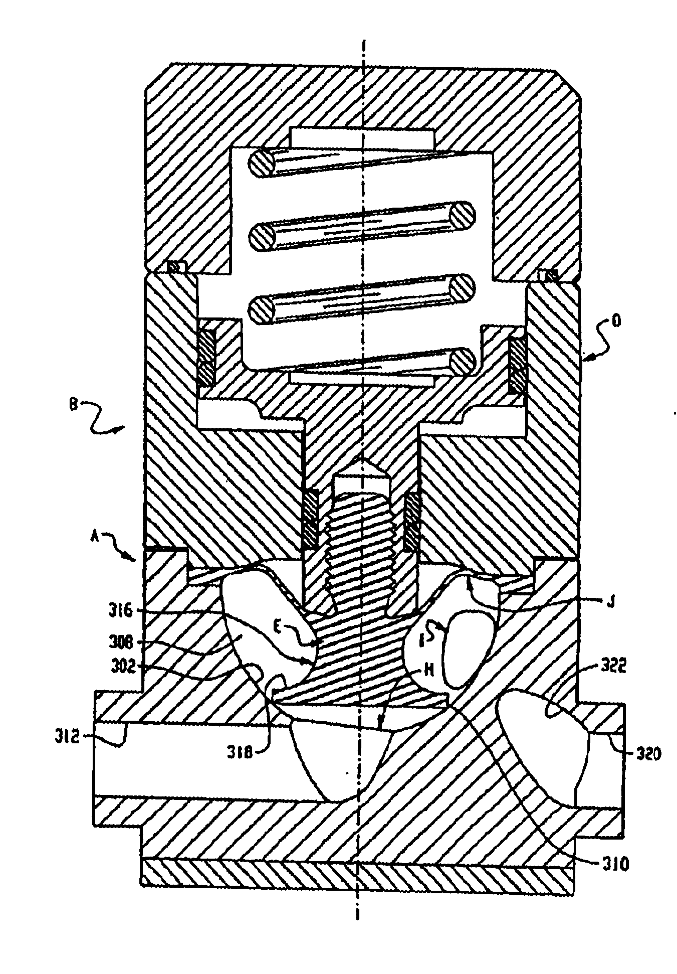
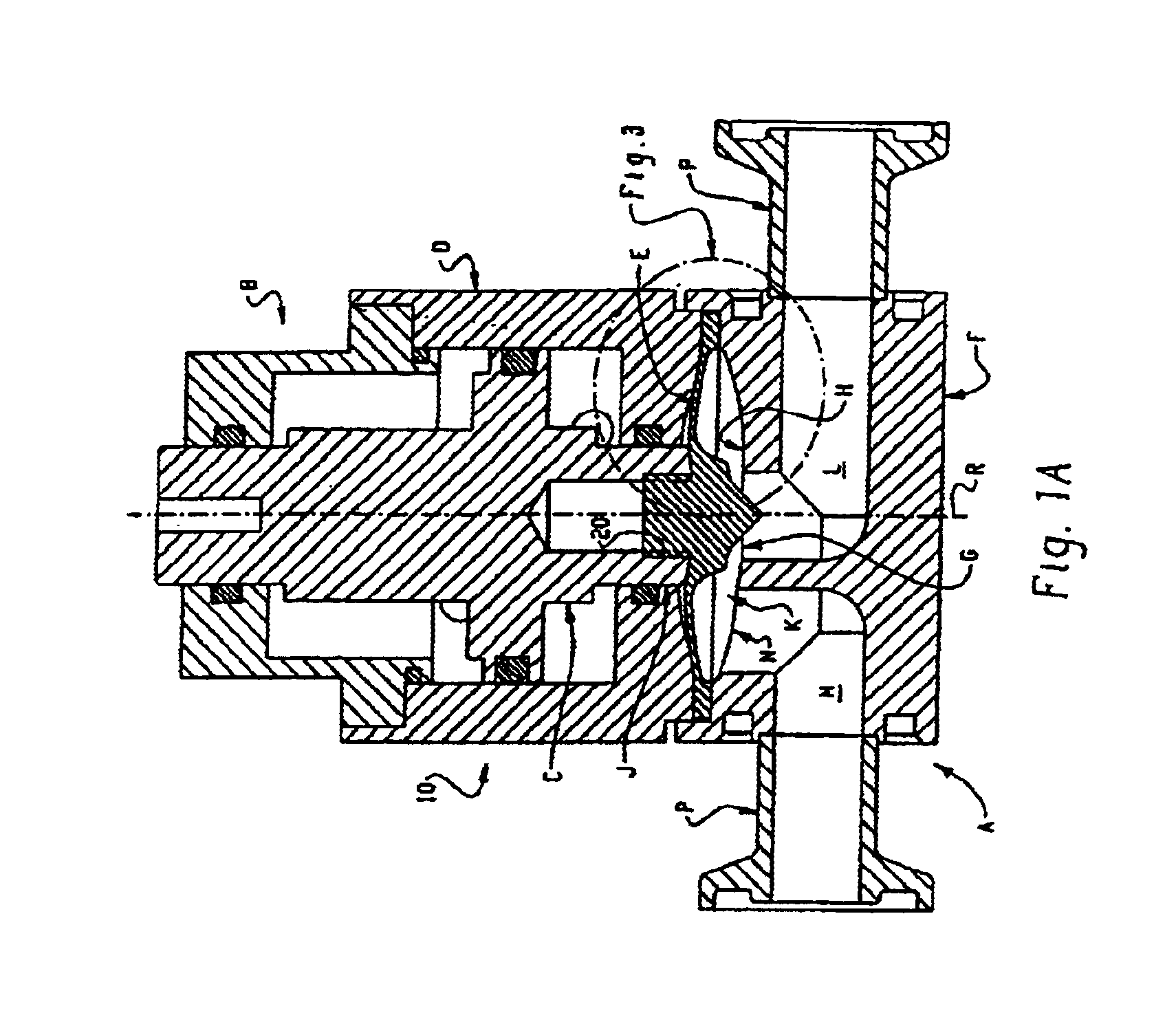
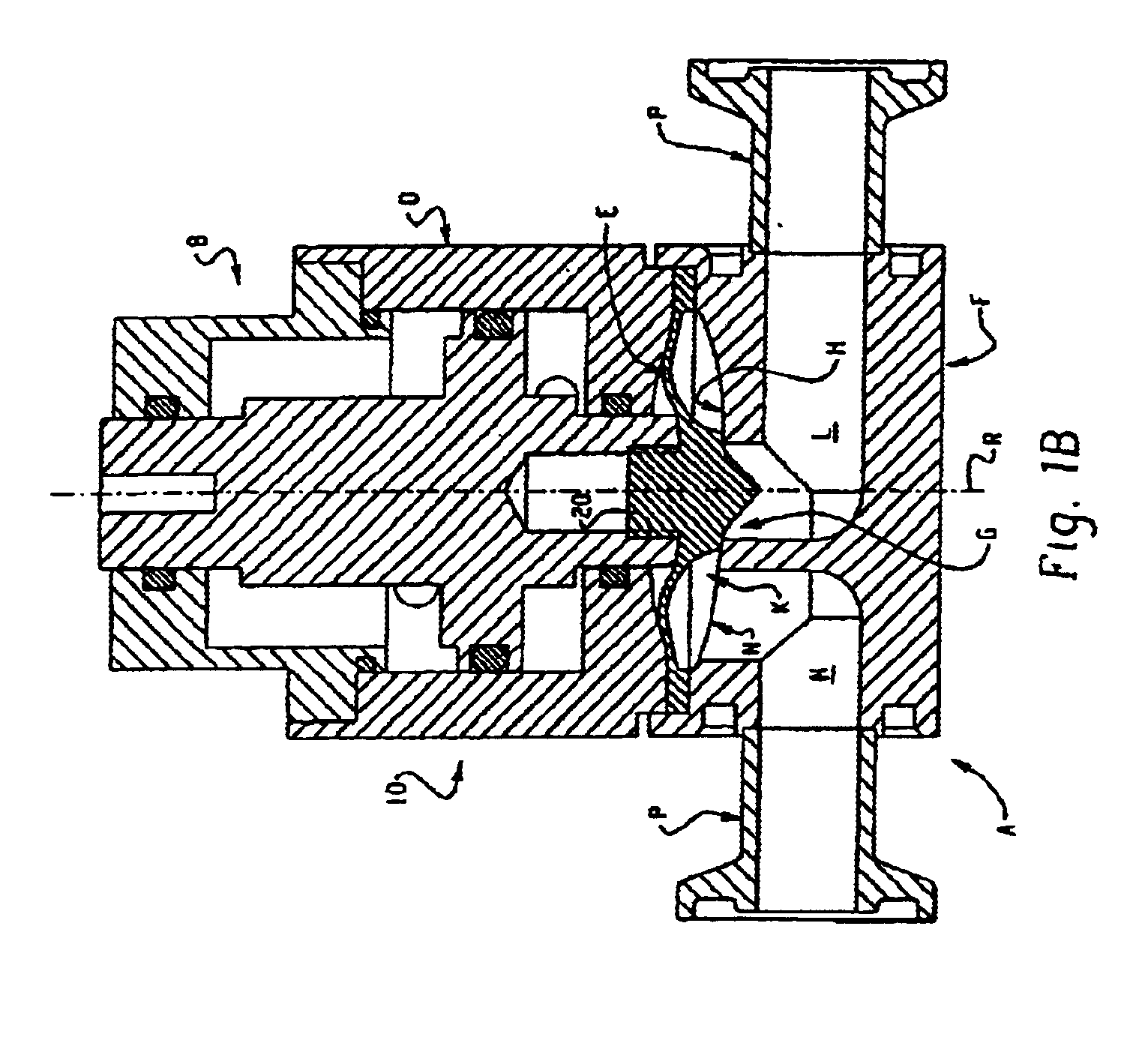
[0029]With reference to FIG. 1A, an embodiment of a diaphragm valve and actuator assembly 10 in accordance with the present invention is illustrated in cross-sectional elevation. The assembly 10 includes a valve A and a valve actuator B. The actuator B includes a valve actuator stem C that axially moves within an actuator housing D to operate a diaphragm E in a valve body F. The valve body F and actuator housing D are mounted together and form the assembled valve A. The diaphragm E closes a port G by being pressed into engagement with a valve seat area H (see FIG. 1B). The general construction and operation of the valve assembly 10 is described in the above-referenced patent “134 and will not be repeated herein. However, the actuator housing D, the diaphragm E and the valve body F have a number of modifications as compared to the corresponding structures in the “134 patent and will be described in detail herein. However, it should be noted that a diaphragm in accordance with the pre...


PUM


Abstract

A sanitary diaphragm valve is provided that includes a generally dome shaped diaphragm having a central boss that can be connected to or driven by a valve actuator. The diaphragm includes an outer peripheral edge and a relatively thin web portion that connects the boss to the outer edge. In one embodiment, the web portion is arcuate or dome shaped. The thinner web portion permits the diaphragm to have an extended cycle life and to permit the valve to operate at higher fluid pressures. The diaphragm may be made from a chemically resistant material and optimized to maintain high flexure.

Description

CROSS REFERENCE TO RELATED APPLICATIONS[0001]This application is a continuation-in-part of U.S. patent application Ser. No. 10 / 109,413, filed on Mar. 28, 2002 for SANITARY DIAPHRAGM VALVE, which is a continuation of U.S. patent application Ser. No. 09 / 231,683 filed on Jan. 14, 1999 now U.S. Pat. No. 6,123,320 for SANITARY DIAPHRAGM VALVE which claims the benefit of U.S. provisional patent application Ser. No. 60 / 103,722 filed on Oct. 9, 1998 for SANITARY DIAPHRAGM VALVE, the entire disclosures of which are fully incorporated herein by reference. This application also claims the benefit of U.S. provisional patent application Ser. No. 60 / 192,785 filed on Mar. 28, 2000 for SANITARY DIAPHRAGM VALVE, the entire disclosure of which is fully incorporated herein by reference.BACKGROUND OF INVENTION[0002]Various fields such as, for example, biotechnology, semiconductor, pharmaceutical, food processing, and medical, require fluid handling systems that are clean and sterile while at the same t...

Claims


Application Information

Patent Timeline
IPC IPC(8): F16K31/122F16K7/12F16K41/00F16K41/12
CPCF16K7/12F16K41/12F16K31/122
Inventor BROWNE, RONNIECARLSON, GEORGE
Owner SWAGELOK CO
Why Eureka
Try Eureka