
Positive locking fitting assembly

Inactive Publication Date: 2005-04-26
EATON INTELLIGENT POWER LIMITED
View PDF113 Cites 52 Cited by
  • Summary
  • Abstract
  • Description
  • Claims
  • Application Information

AI Technical Summary

Benefits of technology

[0021]Another aspect of the positive locking features includes the use of a pair of locking tabs on each jam nut, and a corresponding pair of notches / reliefs formed on each lock nut group whereby a predetermined amount of rotation of the lock nut group with respect to the jam nut results in positive engagement of the locking tabs with the corresponding notches / reliefs. Both visual and audio indicators are provided to confirm positive engagement. The visual indicator includes the use of an indicator stripe placed on a shoulder of the jam nut which allows the user to observe whether the lock nut group has been fully installed over the jam nut. The indicator stripe will essentially be hidden once the lock nut group is fully screwed over the jam nut. For the audible indicator engagement of the locking tabs within the corresponding notches / reliefs result in a distinct clicking sound due to the biased arrangement of the lock nut group whereby the nut body and the lock ring of the lock nut group are biased with respect to one another. A biasing member in the form of a wave spring maintains the lock nut group in positive engagement with the jam nut. The lock nut group can be removed by overcoming the force of the biasing member, and rotating the lock nut group in an opposite unlocking direction.
[0023]The lock nut group includes a number of subcomponents, to include a split retainer, a lock ring, the wave spring mentioned above, and a nut body. The split retainer is retained within the lock ring by an annular slot or shoulder. The wave spring resides within a specified axial area between the lock ring and nut body. The split retainer captures the wave spring on one edge or side of the wave spring. The other side or edge of the wave spring is captured against an interior shoulder of the nut body. Additionally, a plurality of keys or projections are formed on the interior surface of the lock ring which are placed in mating engagement with a corresponding plurality of notches / reliefs formed on the outer surface of the nut body. When the lock nut group is assembled, the lock ring is axially or longitudinally displaceable with respect to the nut body to the extent that the wave spring can be compressed and decompressed within a fixed space or gap between the lock ring and nut body. This displacement allows the locking tabs of the lock nut group to positively lock within the notches of the jam nut, and also allows unlocking by moving the lock ring with respect to the nut body resulting in the notches being disengaged from the locking tabs on the jam nut.

Problems solved by technology

One particularly challenging problem arises for interconnection of fluid carrying members between the various modular components of the aircraft.

Method used


Image

  • Positive locking fitting assembly
  • Positive locking fitting assembly
  • Positive locking fitting assembly

Examples


Embodiment Construction

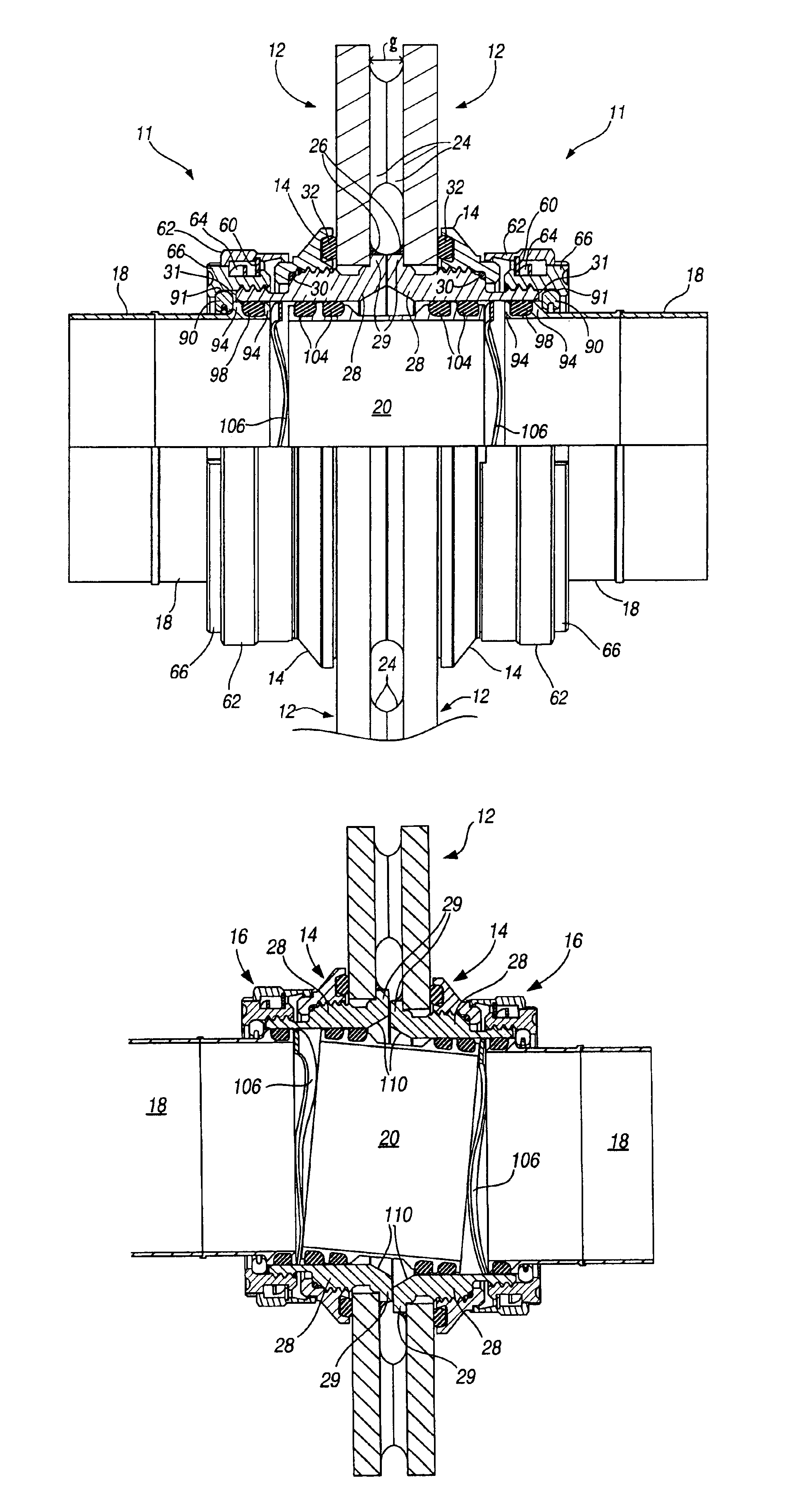
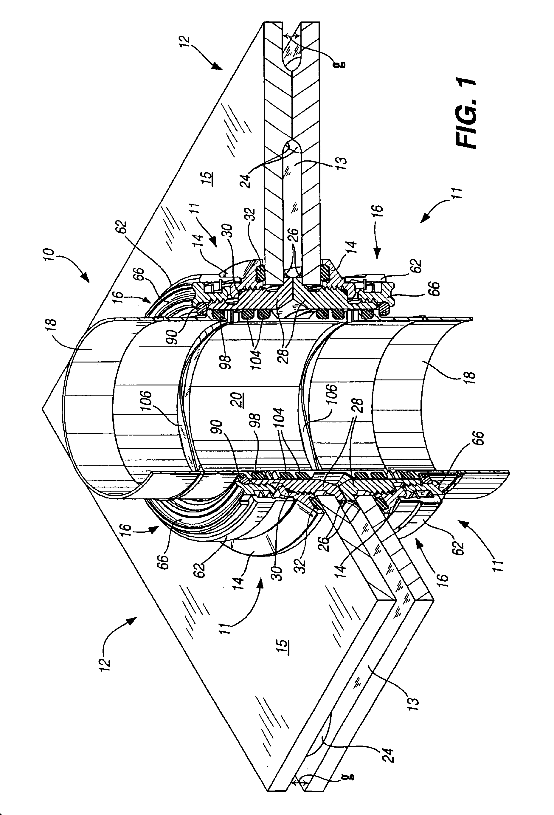
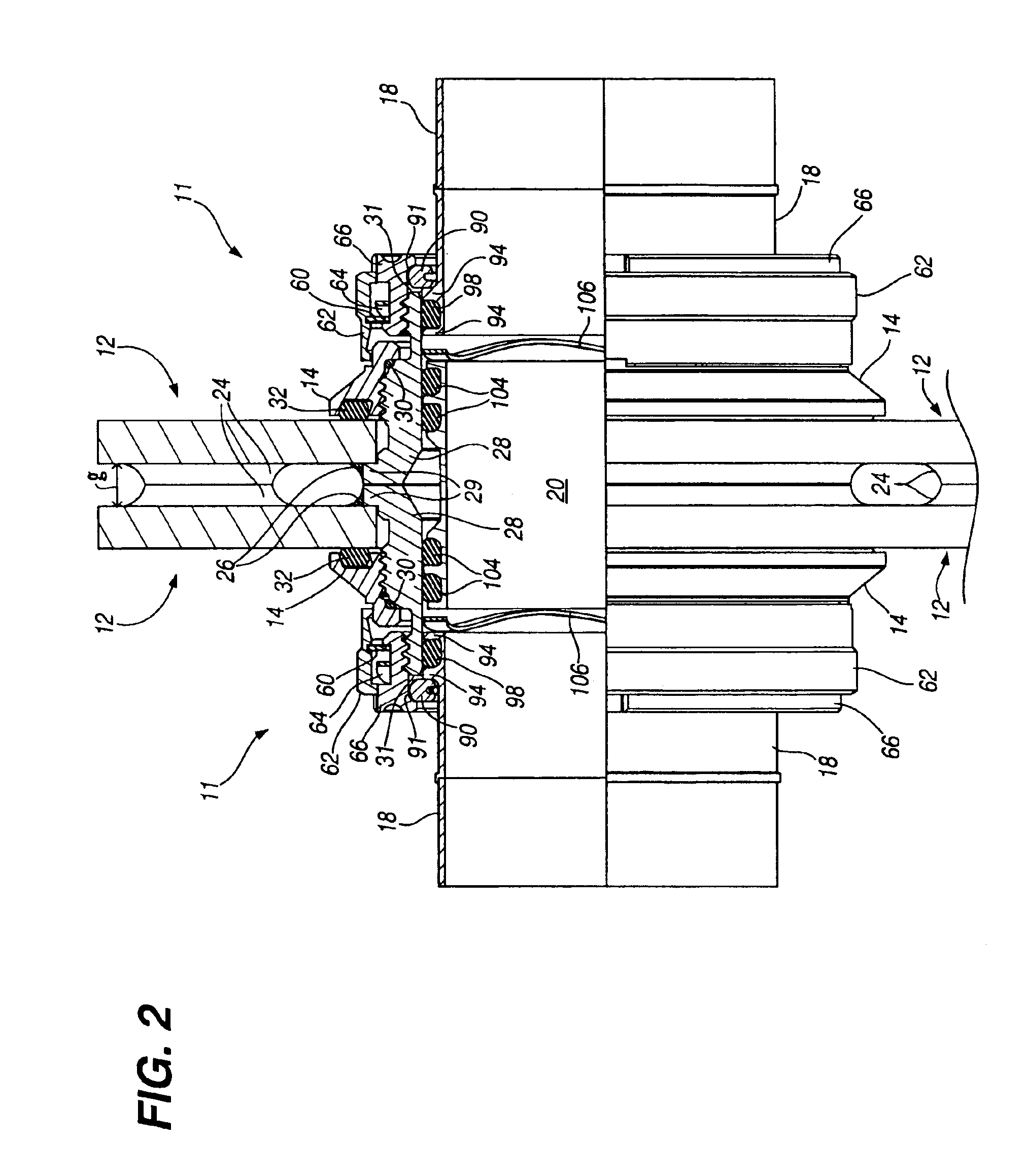
[0045]FIGS. 1 and 2 illustrate the fitting assembly 10 of the present invention installed to provide a leak proof connection between adjacent structures, such as two modular components 12 of an aircraft. A transfer tube 20 interconnects two couplers 11 of the fitting assembly 10 wherein each coupler 11 is of identical construction. Thus, it shall be understood that reference to a single coupler or elements of the coupler applies to both couplers because of their identical construction. Referring also to FIG. 3, an opening or bore 22 is formed through each of the modular components 12. A modular fitting 28 is inserted through each bore. The modular fitting 28 includes an interior flange 29 which contacts the inner surface 13 of the modular component 12. Once the modular fitting 28 is in place, a lock nut group 16 is threadably received over a first or base set of threads 40 on the modular fitting 28. An adjacent tube 18 is secured to each lock nut group 16. The adjacent tube 18 provi...


PUM


Abstract

A positive locking fitting assembly is provided for interconnecting two adjacent structures, such as two modular components of an aircraft. The fitting assembly includes a pair of couplers which attach to the respective modular components, and a transfer tube which interconnects the couplers. Each coupler has a positive locking feature which prevents inadvertent uncoupling during operation. A plurality of redundant seals are incorporated throughout the construction of the fitting assembly which ensures a leak proof relationship not only between the joined pair of modular components, but also through the structure of the elements of the fitting assembly itself.

Description

FIELD OF THE INVENTION[0001]This invention relates to a positive locking fitting assembly for interconnecting two adjacent structures. More particularly, the positive locking fitting assembly relates to a fitting assembly especially adapted for interconnecting modular constructed aircraft to create a leak proof pathway for transfer of fluids between a pair of adjacent modular structures, and further wherein the fitting assembly will not become inadvertently uncoupled due to vibration or other factors experienced through operation of the aircraft.BACKGROUND OF THE INVENTION[0002]Aircraft fuel and hydraulic systems include a large number of couplings or fittings which interconnect various components within the fuel and hydraulic systems. The couplings must be easy to connect and must provide a locking arrangement to prevent inadvertent uncoupling. It is advantageous to provide couplings or fittings which are of minimum weight, simple in construction, and are also easily serviced for r...

Claims


Application Information

Patent Timeline
IPC IPC(8): F16L41/00F16L5/02F16L5/06
CPCF16L5/025F16L41/005F16L5/06F16L2201/20F16L25/01
Inventor BREAY, CLIFTON P.DARBY, THOMAS B.KEENAN, DANIEL E.VAUGHAN, ANTHONY W.
Owner EATON INTELLIGENT POWER LIMITED
Learn More