Lighting apparatus and liquid crystal display

a technology of liquid crystal display and light source, which is applied in the direction of lighting and heating apparatus, instruments, machines/engines, etc., can solve the problems of poor display characteristics of liquid crystal display using the proposed lighting apparatus, the inability of the light source to light the liquid crystal panel, and the inability of the proposed lighting apparatus to have good display characteristics, etc., to achieve uniform light intensity distribution and good display characteristics

Inactive Publication Date: 2005-04-26
FUJITSU LTD
View PDF11 Cites 76 Cited by
  • Summary
  • Abstract
  • Description
  • Claims
  • Application Information

AI Technical Summary

Benefits of technology

[0022]As described above, according to the present invention, angles of the light reflection portions are set so that exit angles of light exiting from the linear photoconductor are required angles, whereby the lighting apparatus can have a uniform light intensity distribution. The application of the lighting apparatus can provide a liquid crystal display of good display characteristics.

Problems solved by technology

However, the above-described proposed lighting apparatus cannot light the liquid crystal panel 108 with a uniform intensity as will be described below.
Accordingly, a liquid crystal display using the proposed lighting apparatus cannot have good display characteristics.

Method used


Image

  • Lighting apparatus and liquid crystal display
  • Lighting apparatus and liquid crystal display
  • Lighting apparatus and liquid crystal display

Examples


first embodiment

[0059]Before the lighting apparatus according to the present invention is explained, the principle of the present invention will be explained.

[0060]The inventors of the present invention have made earnest studies for reasons why the proposed lighting apparatus is unable to light a liquid crystal panel with a uniform light intensity.

[0061]FIG. 33 is a plan view of the proposed light apparatus.

[0062]Light exiting at a 0 degrees exit angle from the planes of light reflection portions 120 formed at the position A which is the center of a linear photoconductor 114 was traced back, and the traces of the light reached substantially the center of the LED 112a.

[0063]Light exiting at, e.g., a 3 degrees exit angle from the planes of light reflection portions 120 formed at the position C which is near the left end of the linear photoconductor 114 was traced back, and the traces of the light reached substantially the center of the LED 112a. An emission angle of the traced back light was 3 degre...

second embodiment

[0095][A Second Embodiment]

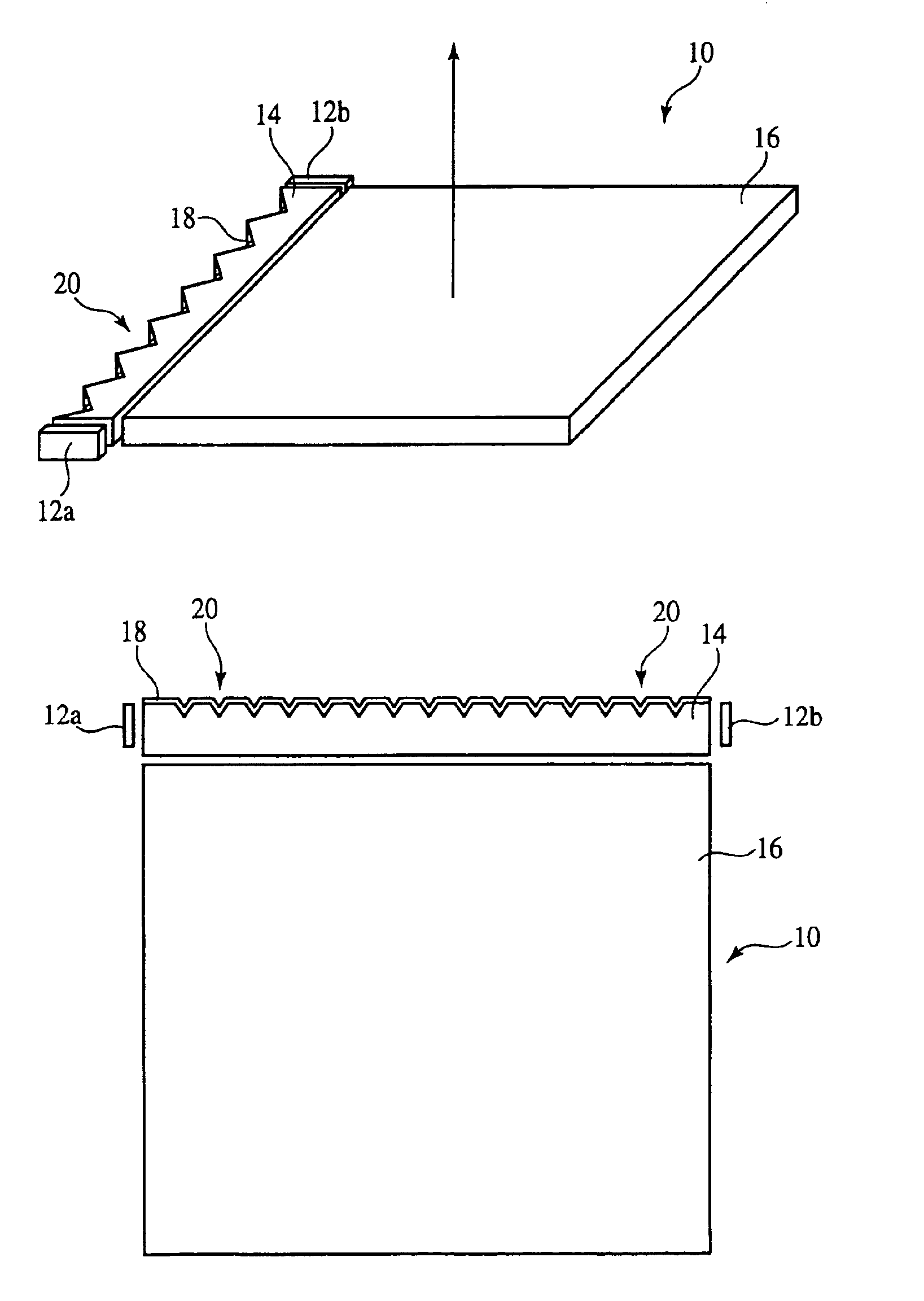
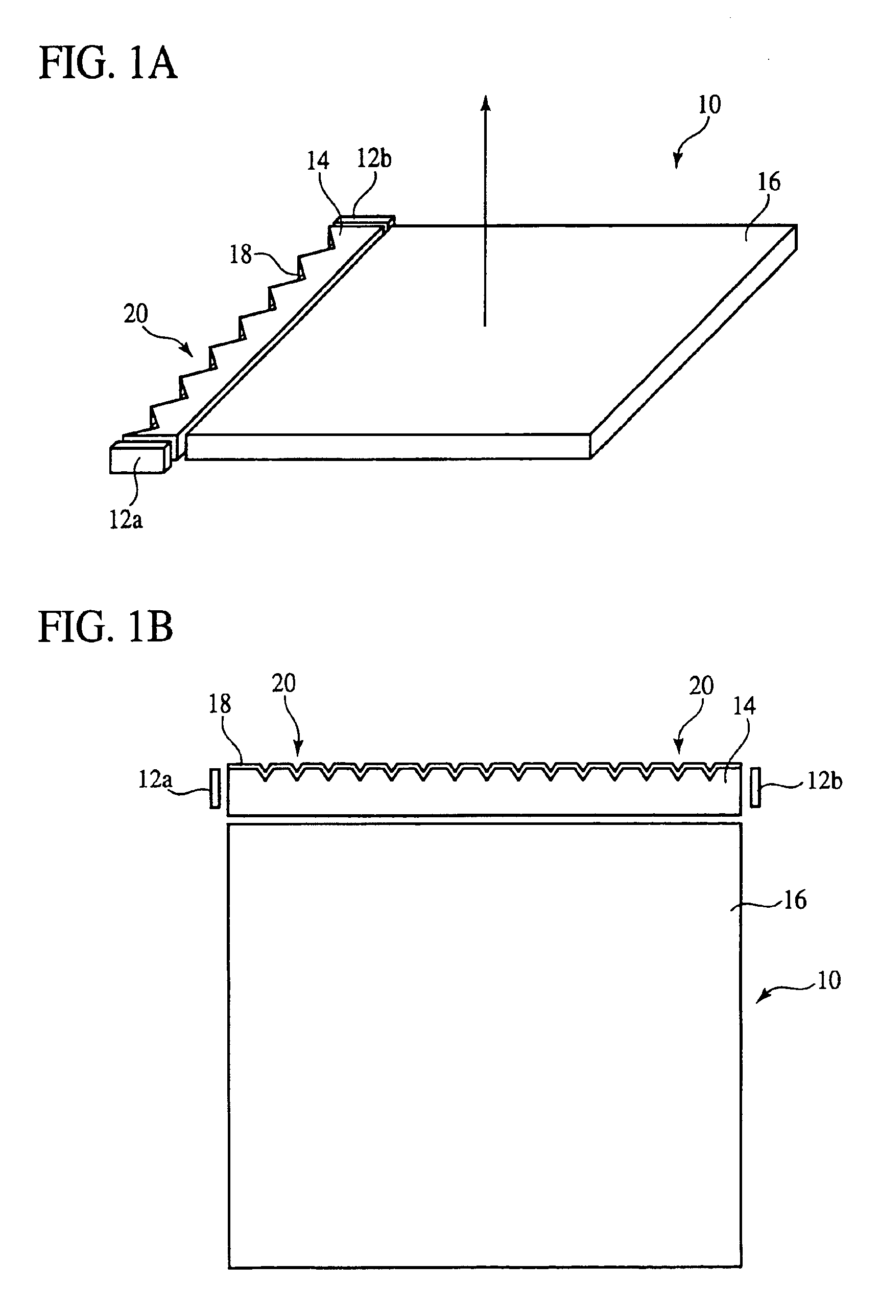
[0096]The lighting apparatus according to a second embodiment of the present invention will be explained with reference to FIGS. 7 to 9. FIG. 7 is a plan view of the lighting apparatus according to the present embodiment. FIG. 8 is a conceptual view of relationships between the human eyes and a display screen. FIG. 9 is a graph of examples of tilt angles of planes of light reflection portions of the lighting apparatus according to the present embodiment. The same members of the present embodiment as those of the lighting apparatus according to the first embodiment are represented by the same reference numbers not to repeat or to simplify their explanation.

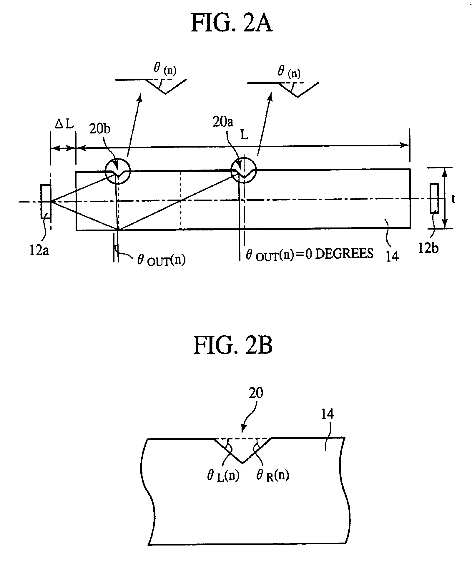
[0097]The lighting apparatus according to the present embodiment is characterized mainly in that tilt angles θ(n) of the planes of the light reflection portions 20 are respectively set so that light exits from a linear photoconductor 14 at a 0 degrees exit angle θOUT(n), i.e., in a direction vertical to t...

third embodiment

[0106][A Third Embodiment]

[0107]The lighting apparatus according to a third embodiment of the present invention will be explained with reference to FIGS. 10 and 11. FIG. 10 is a plan view of the lighting apparatus according to the present embodiment. FIG. 11 is a graph of examples of tilt angles of the planes of light reflection portions of the lighting apparatus according to the present embodiment. The same members of the present embodiment as those of the first or the second embodiment are represented by the same reference numbers not to repeat or to simplify their explanation.

[0108]The lighting apparatus according to the present embodiment is characterized mainly in that tilt angles θ(n) of the planes of light reflection portions are set so that light is incident from LEDs 12a, 12b directly on all light reflection portions 20c among the light reflection portions 20c, and the light is totally reflected on the light reflection portions 20c to exit from the exit side of a linear pho...


PUM

PropertyMeasurementUnit
sizeaaaaaaaaaa
exit angleaaaaaaaaaa

Abstract

A lighting apparatus 10 comprising light sources 12a, 12b for emitting light, a plurality of light reflection portions 20 formed on the reflection side for reflecting light incident from the light sources, and a linear photoconductor 14 for causing the light to exit from the exit side opposed to the reflection side, the planes of the plurality of reflection portions being respectively tilted at angles which converge the light to the human eyes watching. Angles of the light reflection portions are set so that exit angles of light exiting from the linear photoconductor are required angles, whereby the lighting apparatus can have a uniform light intensity distribution. The application of the lighting apparatus can provide a liquid crystal display of good display characteristics.

Description

BACKGROUND OF THE INVENTION[0001]The present invention relates to a lighting apparatus and a liquid crystal display, more specifically to a lighting apparatus which can light with a uniform light intensity, and a liquid crystal display using the lighting apparatus.[0002]Liquid crystal panels, which are thin and light, are widely used as display screens of portable information terminals.[0003]The liquid crystal panels contain transmission type liquid crystal panels and reflection type liquid crystal panels.[0004]FIG. 28A is a sectional view of the transmission type liquid crystal panel. As shown in FIG. 28A, a deflector 214 is sandwiched between a glass substrate 210 and a glass substrate 212. Bus lines 216, etc. are formed on the glass substrate 212. Liquid crystal 220 is sealed between the glass substrate 212 and the glass substrate 218. A color filters 224a, 224b, 224c are sandwiched between the glass substrate 218 and the glass substrate 222. A deflector 228 is sandwiched between...

Claims


Application Information

Patent Timeline
Patent Type & Authority Patents(United States)
IPC IPC(8): G02F1/1335G02F1/13G02B6/00F21V8/00F21Y101/02G02F1/13357
CPCG02B6/0028G02F1/133615G02B6/0038G02B6/0068G02F1/1335
Inventor MAEDA, SATOSHIARITAKE, HIROKAZUSATAKE, TAKAO
Owner FUJITSU LTD
Why Eureka
Try Eureka