
Apparatus for rectification of liquid mixtures and/or for . . .

Inactive Publication Date: 2005-04-26
JENSEN ERIK
View PDF26 Cites 9 Cited by
  • Summary
  • Abstract
  • Description
  • Claims
  • Application Information

AI Technical Summary

Benefits of technology

[0009]The calculation of the dimensions of an apparatus is normally based on a vapour flow rate of about 1 m / sec. When, for example, the specific weight of the vapour phase is 1 kg / m3 a pressure difference of only 0.05 kg / m2 and 0.82 kg / m2 (equal to 0.82 mm water column) is necessary for obtaining a vapour flow rate of about 1 m / sec. and 4 m / sec., respectively. Thus, a very small pressure increase may cause a substantially re-circulation of the vapour whereby the efficiency is reduced. Therefore, it would be advantageous to be able to obtain a more efficient control of the vapour flow through the apparatus.
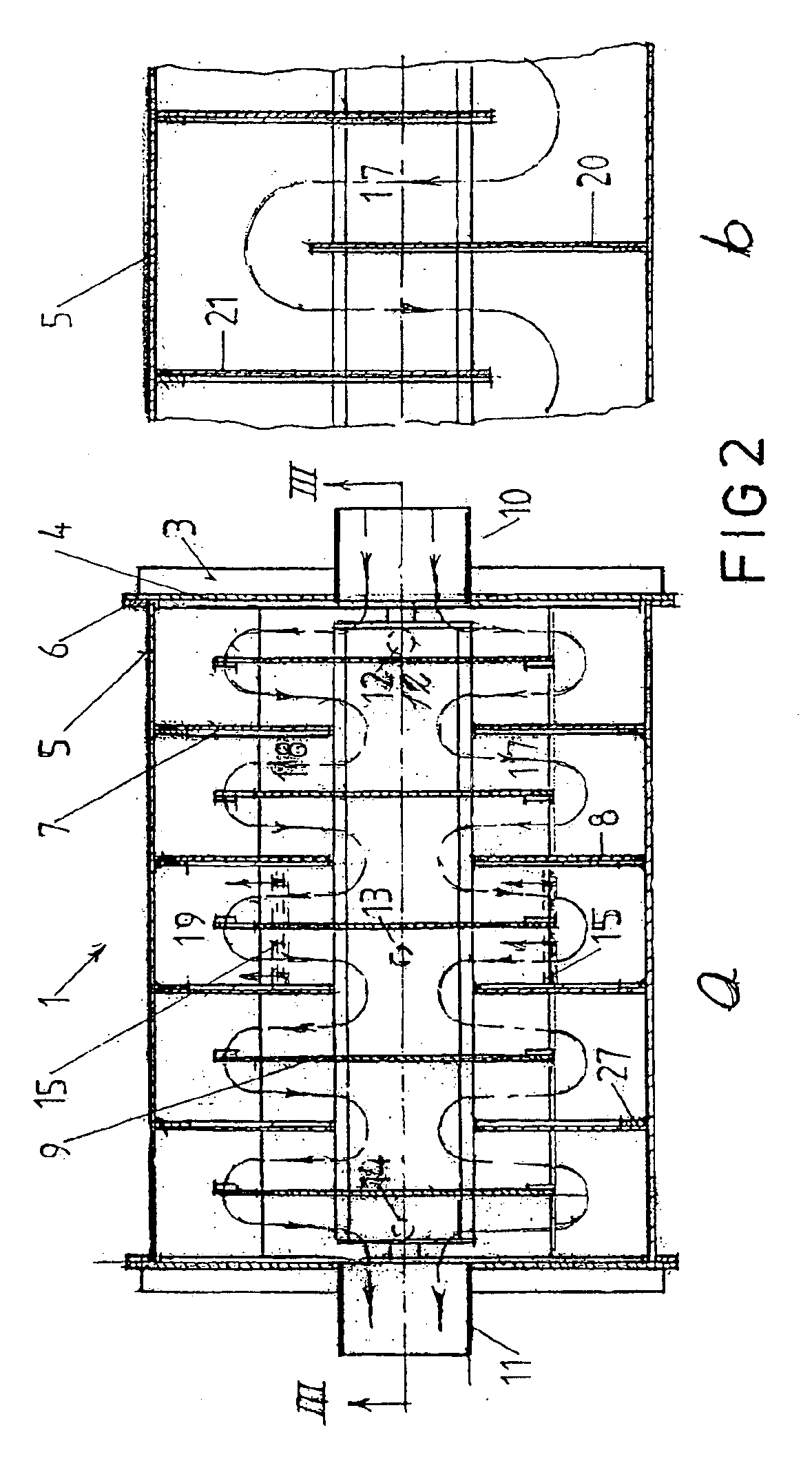
[0011]The guide plates provided in the apparatus according to the invention counteract the undesired axial re-circulation of gas phase due to the small radial pressure difference caused by the liquid being thrown radially outwardly towards the inner wall of the processing chamber as explained above. Thus, the guide plates render it possible to obtain a stepwise, controlled axial flow of the gas phase.
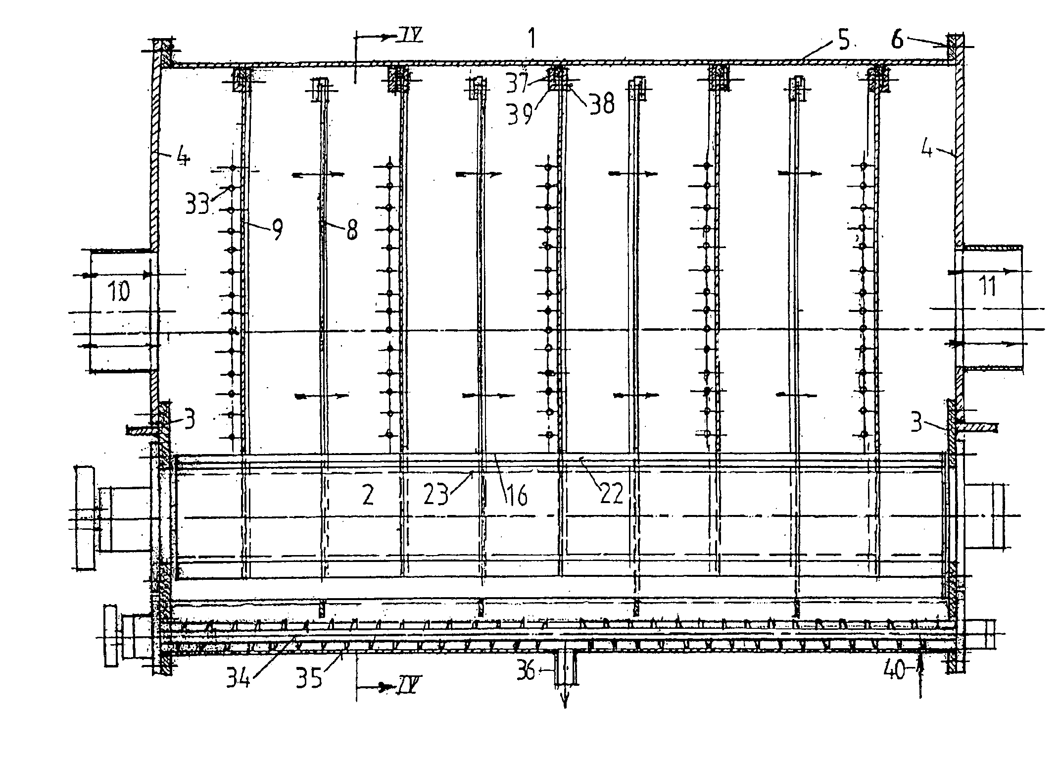
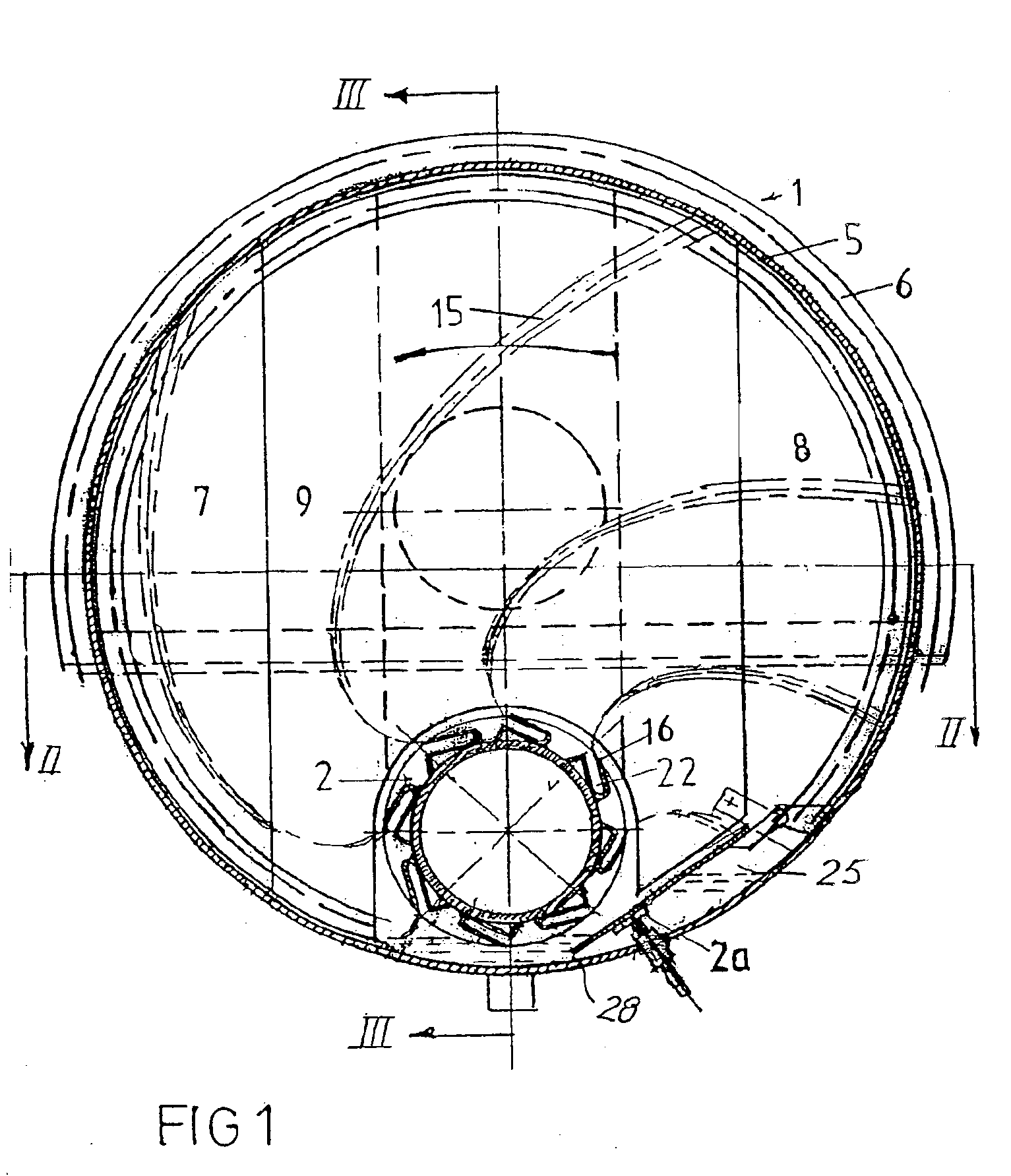
[0015]The rotor may be arranged at the bottom of the processing chamber where liquid having been thrown against the peripheral wall of the processing chamber be collected for recirculation. The lower part of the rotor may then dip into the liquid. This may, however, cause undesired vibrations of the liquid. In the preferred embodiment the liquid application means comprise a liquid receiving chamber for receiving liquid flowing downwards along the inner peripheral wall of the processing chamber, the receiving chamber communicating with the liquid channel via an adjustable, longitudinally extending opening or slot. In this manner the flow of re-circulated liquid to the rotor may be controlled and stabilised. The liquid receiving chamber, may for example, be defined between the peripheral inner wall of the processing chamber and a flap or plate member, which is pivotal about a longitudinal axis so as to allow adjustment of a space defined between the lower edge of the flap member and the adjacent part of the inner wall of the processing chamber. This allows for the desired control of the liquid supply in a very simple manner. The flap or plate member and the adjacent part of the peripheral wall may define an upwardly open liquid collecting channel allowing for the desired axial transport of liquid through the processing chamber.

Problems solved by technology

Thus, a very small pressure increase may cause a substantially re-circulation of the vapour whereby the efficiency is reduced.

Method used


Image

  • Apparatus for rectification of liquid mixtures and/or for . . .
  • Apparatus for rectification of liquid mixtures and/or for . . .
  • Apparatus for rectification of liquid mixtures and/or for . . .

Examples


Embodiment Construction

[0027]The embodiments of the apparatus according to the invention shown in the drawings comprise a preferably cylindrical housing 1 having a substantial horizontal, longitudinal axis. A liquid application device or atomising device 2a is arranged within the housing and includes a rotor 2 rotatably journalled in housing end walls 3 at the bottom of the housing. The lower part of the end walls 3 is formed as an integral part of the housing, while the upper parts of the housing end walls are in the form of covers 4 which may be bolted or otherwise releasably fastened to flanges 6. The end covers 4 are provided with a vapour inlet 10 and a vapour outlet 11. The vapour inlet 10 may be connected to an evaporator section (not shown) and the vapour outlet at the opposite end may be connected to a condenser (not shown) or possibly to the suction side of a heat pump. The housing 1 is divided into sections or chambers by means of axially spaced guide plates 7, 8 or 9. The end openings covered ...


PUM

PropertyMeasurementUnit
Lengthaaaaaaaaaa
Dimensionaaaaaaaaaa

Abstract

An apparatus for rectification liquids and / or for scrubbing of gases has an elongated, horizontally extending, cylindrical process chamber or housing. A liquid and a gaseous phase are passed counter-currently through the apparatus. The liquid is thrown outwardly towards the peripheral housing wall by a rotor extending along the bottom of the housing. Liquid flowing downwards along the peripheral housing wall is collected in an upwardly open channel and the liquid collected therein may be supplied to the rotor via an adjustable slot or opening. Transversely extending, axially spaced guide plates are arranged within the housing so as to define a tortuous path for the gas phase flowing through the housing.

Description

REFERENCE TO RELATED APPLICATIONS[0001]The present application is the national stage under 35 U.S.C. 371 of international application PCT / DK00 / 00086, filed Mar. 1, 2000 which designated the United States, and which international application was published under PCT Article 21(2) in the English language.BACKGROUND OF THE INVENTION[0002]1. Technical Field of the Invention[0003]The present invention relates to an apparatus for rectification of liquid mixtures and / or for scrubbing of gases.[0004]2. Prior Art[0005]Apparatuses for rectification of liquid mixtures and apparatuses for scrubbing of gases function in principle in the same way, namely by causing the atomised liquid and the gas phase to flow counter-currently and thus to come into mutual contact. The reason why apparatuses for rectification and apparatuses for gas scrubbing have usually been built differently is that the reaction between the gas and the liquid phases is different in the two kinds of apparatuses. In rectification...

Claims


Application Information

Patent Timeline
IPC IPC(8): B01D47/00B01D47/18B01D3/00B01D3/34B01D3/08
CPCB01D3/08B01D47/18B01D3/346B01D53/78B01D53/18
Inventor JENSEN
Owner JENSEN ERIK
Learn More