Multi-layer ceramic heater element and method of making same

a ceramic heater element and multi-layer technology, applied in the field of ceramic heater elements, can solve the problems of residual stress, non-uniform attachment, and event failure of glow plugs, and achieve the effects of limiting the heating of the resistive layer, high conductive, and better and more reliable heat concentration

Inactive Publication Date: 2005-04-26
CHONGGING LE MARK CERAMIC TECH
View PDF8 Cites 32 Cited by
  • Summary
  • Abstract
  • Description
  • Claims
  • Application Information

AI Technical Summary

Benefits of technology

[0007]Generally, the present invention provides a ceramic heater element and a glow plug incorporating a novel heater element. The heater element has a base portion and a heater portion. Conductive, insulative and resistive layers extend through both the base and heater portions. An outer conductive layer is applied to the outside of the base portion to provide a highly conductive return path. This tends to limit the heating of the resistive layer in the base portion and results in better and more reliable heat concentration in the heater portion. A waterproof non-conductive outer layer is provided over the outer surface of the heater element. The heater element can be assembled to form a glow plug for a diesel engine.

Problems solved by technology

Used in a glow plug, they experience cyclic heating and cooling, which results in high internal stresses at the interfacial junction between the ceramic layers, promoting eventual failure of the glow plugs.
Further, residual stresses are the result of manufacture, particularly from uneven contraction in the cooling period which occurs below the plastic deformation state of the ceramic composition, and from non-uniform attachment between the layers.
While the ceramic heater described in this application has reduced internal stresses, it has been found to be difficult to manufacture to the stringent standards required of such heaters.
In particular, the layer thicknesses are difficult to control precisely, and even minor discrepancies can lead to widely varying heat output in the final heater.
Additionally, it has been found that the performance of prior ceramic heater elements can be affected by moisture.

Method used


Image

  • Multi-layer ceramic heater element and method of making same
  • Multi-layer ceramic heater element and method of making same
  • Multi-layer ceramic heater element and method of making same

Examples


Embodiment Construction

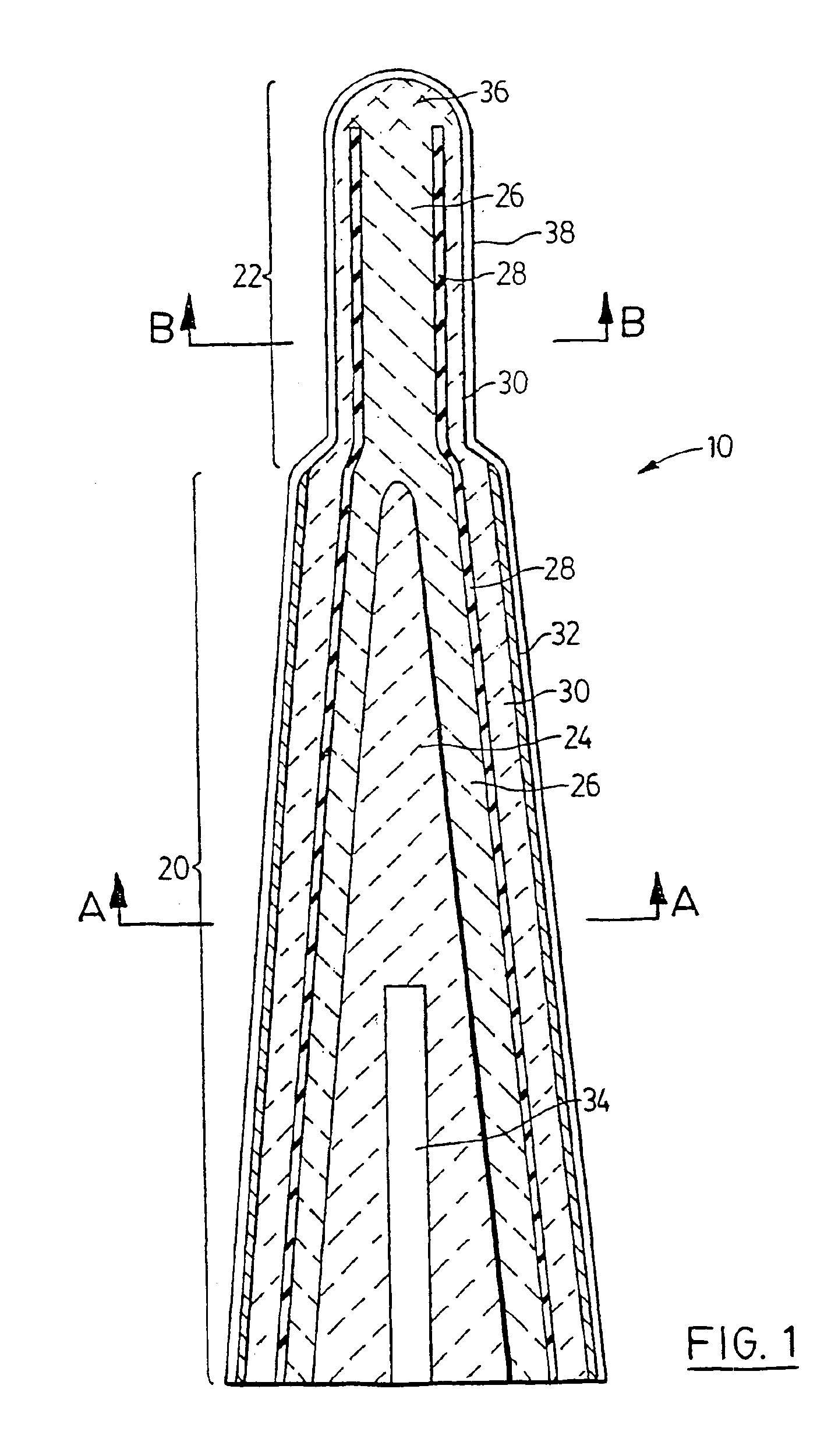
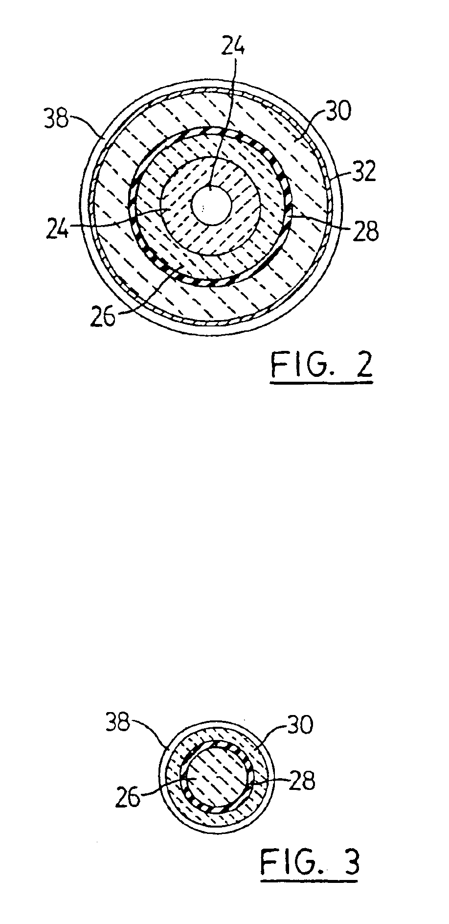
[0016]The present invention will be now be described with reference to FIGS. 1 and 2. A schematic view of a ceramic heater element according to a first embodiment of the present invention is shown in cross-section along its longitudinal axis in FIG. 1, and in cross-section along line A—A in FIG. 2. The heater element is not shown to scale and is generally designated at reference numeral 10.

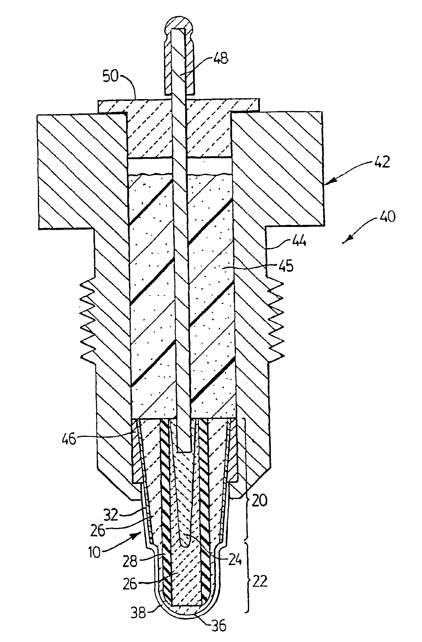
[0017]Element 10 consists of a base portion 20 and a heater portion 22. Base portion 20 and heater tip portion 22 form a generally cylindrical heater element that is thicker in diameter through base portion 20 and tapers to a thinner diameter heater portion 22. As is well known to those of skill in the art, base portion 20 is typically sized to be received in a metal housing, including appropriate electrical contacts, to form a glow plug for a diesel engine. As described in U.S. Pat. No. 5,880,432, entitled “Electric heating device with ceramic heater wedgingly received within a metallic body”, th...


PUM


Abstract

A ceramic heater element and a glow plug incorporating the novel heater element. The heater element has a base portion and a heater portion. Conductive, insulative and resistive layers extend through both the base and heater portions. An outer conductive layer is applied to the outside of the base portion to provide a highly conductive return path. This lends to limit the heating of the resistive layer in the base portion and results in better and more reliable heat concentration in the heater portion. The heater element is further provided with a waterproof non-electrically conductive outer layer. The heater element can be assembled to form a glow plug for a diesel engine.

Description

FIELD OF THE INVENTION[0001]This invention relates to ceramic heater elements. In particular, this invention relates to ceramic heater elements, and methods of manufacture therefor, such as ceramic heaters used in high-temperature a glow plugs for diesel engines.BACKGROUND OF THE INVENTION[0002]It is well known to manufacture ceramic glow plugs having a multi-layered construction. Examples of such conventional glow plugs are described in U.S. Pat. Nos. 4,742,209, 5,304,778 and 5,519,187. In general, these glow plugs have a ceramic heater with a conductive core enclosed by insulative and resistive ceramic layers, respectively. The layers are separately cast and fitted together. The resulting green body is then sintered to form a ceramic heater. Such ceramic heaters suffer several drawbacks. Used in a glow plug, they experience cyclic heating and cooling, which results in high internal stresses at the interfacial junction between the ceramic layers, promoting eventual failure of the g...

Claims


Application Information

Patent Timeline
Patent Type & Authority Patents(United States)
IPC IPC(8): F23Q7/00H05B3/14
CPCF23Q7/001H05B3/141H05B2203/027
Inventor LEIGH, PETER
Owner CHONGGING LE MARK CERAMIC TECH
Why Eureka
Try Eureka