Cholesteric liquid crystal display system

a liquid crystal display and liquid crystal display technology, applied in liquid crystal compositions, instruments, chemistry apparatuses and processes, etc., can solve the problems of complex electronic drives, slow sequential writing of data lines, and inability to write data lines in parallel, so as to improve image quality, simple sheet structure, and fast writing process

Inactive Publication Date: 2005-04-26
IND TECH RES INST
View PDF16 Cites 33 Cited by
  • Summary
  • Abstract
  • Description
  • Claims
  • Application Information

AI Technical Summary

Problems solved by technology

Sequentially writing data lines is slow compared to writing all pixels at once and requires electrical drivers on each column and row line.
Prior art light sensitive sheets have required expensive and complex photosensitive layers for operation.
Electrical drive systems must write data sequentially, requiring complex electronic drives.

Method used


Image

  • Cholesteric liquid crystal display system
  • Cholesteric liquid crystal display system
  • Cholesteric liquid crystal display system

Examples


Embodiment Construction

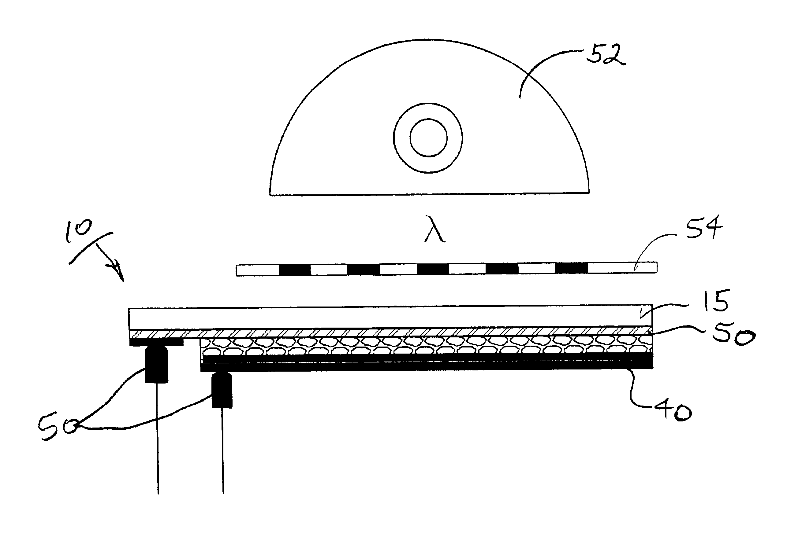
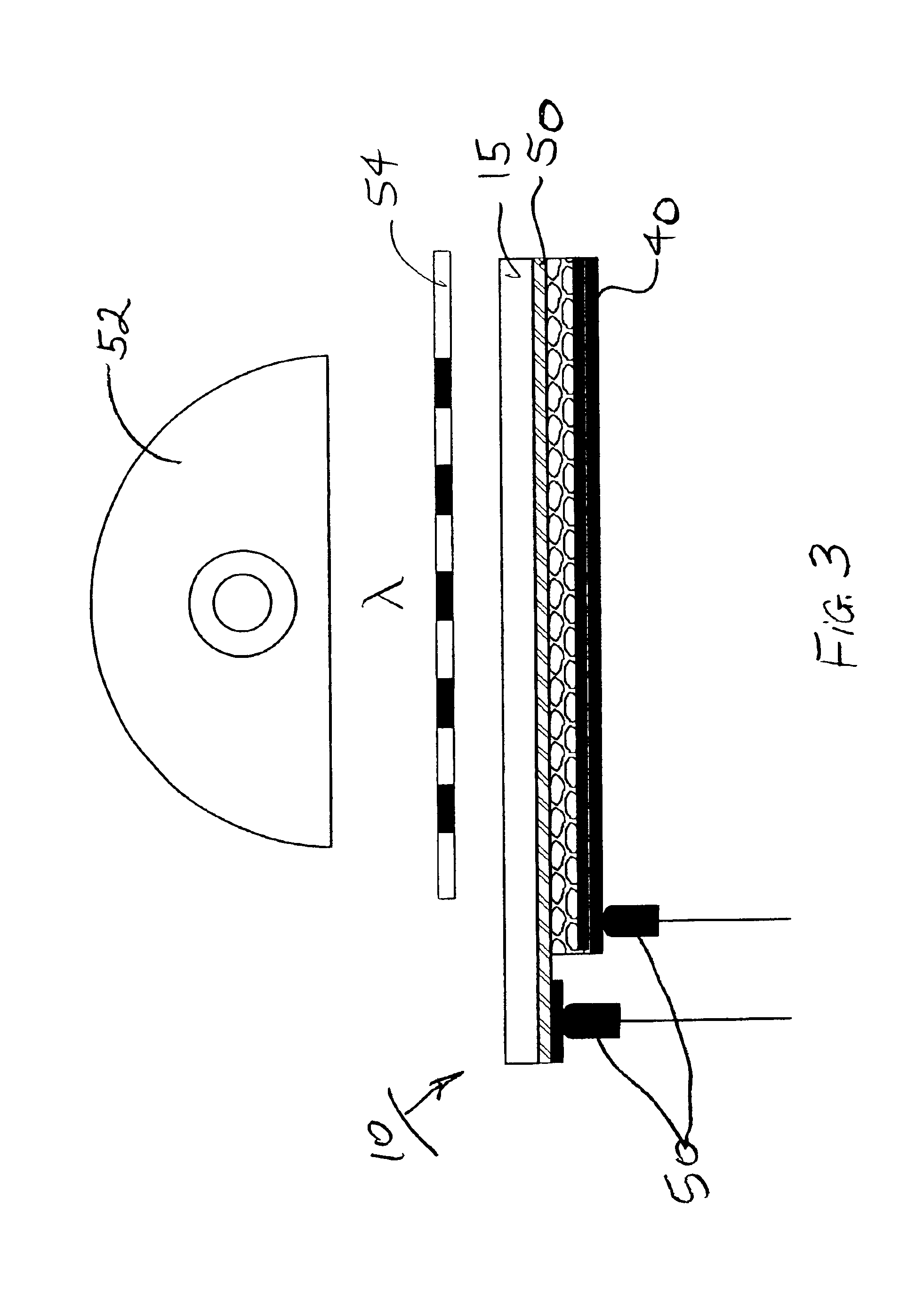
[0023]Referring to FIG. 1, a display 10 according to the present invention includes a display substrate 15, such as a thin transparent polymeric material, for example, Kodak Estar film base formed of polyester plastic that has a thickness of between 20 and 200 (preferably 125 microns). Other polymers, such as transparent polycarbonate, can also be used.

[0024]A first transparent conductor 20 is formed on display substrate 15. First transparent conductor 20 can be tin-oxide, indium-tin-oxide (ITO), or polythiophene, with ITO being the preferred material. Typically the material of first transparent conductor 20 is sputtered or coated as a layer over display substrate 15 having a resistance of less than 1000 ohms per square.

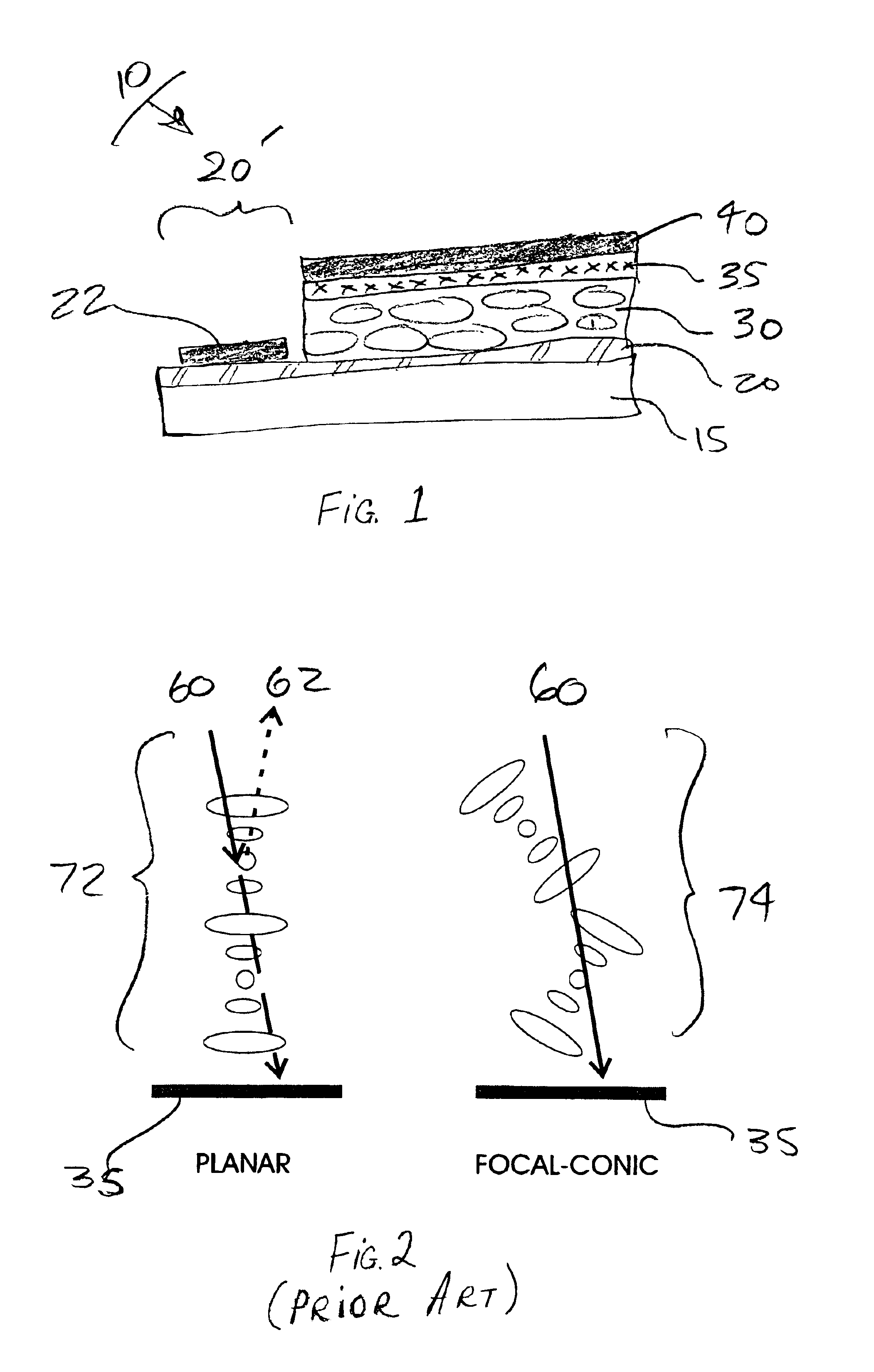
[0025]In a preferred embodiment, a first conductor cover 22 is printed over first transparent conductor 20. First conductor cover 22 can be screen printed conductive ink such as Electrodag 423SS screen printable electrical conductive material from Acheson Corporation...


PUM

PropertyMeasurementUnit
thicknessaaaaaaaaaa
thicknessaaaaaaaaaa
diameteraaaaaaaaaa

Abstract

A display system includes a display arranged to receive an image wise pattern of light to form an image, including, a pair of conductors, at least one conductor being transparent, a layer of cholesteric liquid crystal material disposed between the conductors, the liquid crystal material having multiple stable optical states at zero electrical field, and a light absorber for forming an image wise thermal pattern in the liquid crystal sufficient to change the optical state of the cholesteric liquid crystal in response to an image wise pattern of light; a display writer, including, a light source for producing a flash of light of sufficient intensity to generate sufficient heat in the light absorber to change the optical state of the cholesteric liquid crystal, a mask located between the light source and the display for defining the image wise pattern of light, a display drive connectable to the conductors for generating an electric field between the conductors for changing the optical state of the cholesteric liquid crystal, and a controller connected to the light source and the display drive for controlling the intensity of the electrical field and actuating the light source to create an image on the display.

Description

FIELD OF THE INVENTION[0001]The present invention relates to a display system having a polymer dispersed cholesteric liquid crystal that change optical states in response to heat, light and electrical field.BACKGROUND OF THE INVENTION[0002]Cholesteric liquid crystals have the property of maintaining several different optical states in the absence of electrical field. Additionally, cholesteric liquid crystals can change optical states in response to applied electrical and / or thermal fields. Those properties make them useful in the development of field-stable, re-writable displays.[0003]U.S. Pat. No. 3,401,262 issued Sep. 10, 1968 to Fergason et al. discloses a cathode ray tube to apply light to a screen. The screen has a photoconductive layer that is excited by an electrical field applied by fine leads across the photoconductive layer. The screen has a layer of a temperature sensitive cholesteric material that changes reflective wavelength with slight changes in temperature, and chan...

Claims


Application Information

Patent Timeline
Patent Type & Authority Patents(United States)
IPC IPC(8): G02F1/1334G02F1/13G02F1/137G02F1/133
CPCG02F1/13718G02F1/1334G02F1/137
Inventor STEPHENSON, STANLEY W.MI, XIANG-DONGJOHNSON, DAVID M.
Owner IND TECH RES INST
Why Eureka
Try Eureka