
Method and device for orienting a digital panoramic image

a digital panoramic and image technology, applied in the field of digital photography, can solve the problems of difficult alignment, high cost of 360° lenses, and inability to obtain alignment, and achieve the effects of convenient wide-angle photography, low cost price, and simple structur

Inactive Publication Date: 2005-04-26
6115187 CANADA
View PDF23 Cites 78 Cited by
  • Summary
  • Abstract
  • Description
  • Claims
  • Application Information

AI Technical Summary

Benefits of technology

[0017]The present invention also comprises a method and a device that facilitate the taking of wide-angle photographs without parallax errors, without the need to make the usual and delicate adjustments of the position of the camera to obtain t

Problems solved by technology

Disadvantages of the Photography Equipment
It must be specified here that obtaining a 360° digital panoramic image generally requires taking at least two 180° photographs (or N photographs taken with an angle of 360° / N) by means of a panoramic lens and a pan head, as 360° lenses are expensive and have a small camera angle in the vertical plane.
Yet, this alignment is not easy to obtain and requires several adjustments and tests.
Furthermore, the pan heads are precision instruments that are quite considerable in price.
Furthermore, SLR (“Single Lens Reflex”) type digital cameras can receive any type of lens but they are expensive and not very accessible to the general public, which generally turns towards compact digital cameras, i.e. with a fixed lens.
Unfortunately, these adapters are not universal and many compact cameras cannot receive them as they do not have the required thread.
Disadvantages of the Differences in Color between Panoramic Images
Another disadvantage of the above-mentioned techniques relates to the correction of the colors of the panoramic images obtained by assembling wide-angle photographs.
Disadvantages of the Orientation of Panoramic Images in a Virtual Visit
Another problem of the above-mentioned techniques, occurring in a virtual visit, is that the observer is subject to a phenomenon of disorientation during a transition from one panoramic image to the other, as he has no common point of reference between the different panoramas.
The problem is to define the portion of panoramic image to be displayed on the screen when the observer enters a panoramic image.

Method used


Image

  • Method and device for orienting a digital panoramic image
  • Method and device for orienting a digital panoramic image
  • Method and device for orienting a digital panoramic image

Examples


Embodiment Construction

[0073]I. Description of a Camera Support Device According to the Present Invention

[0074]a. Principal Aspects of the Support Device

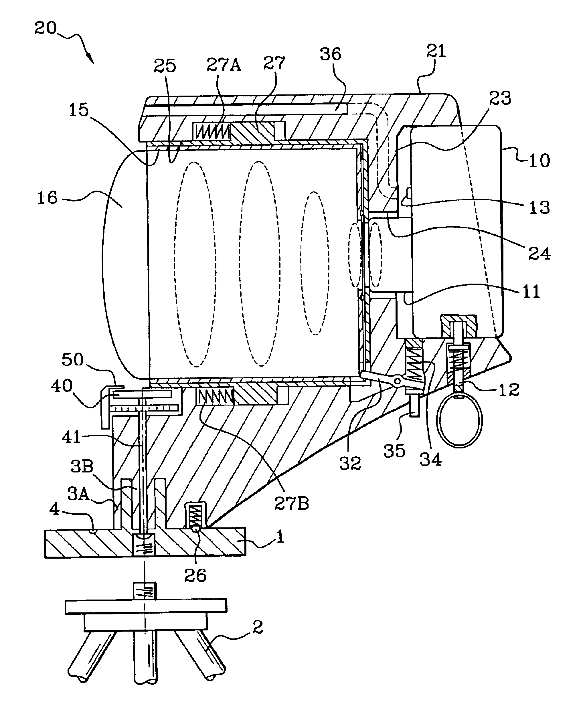
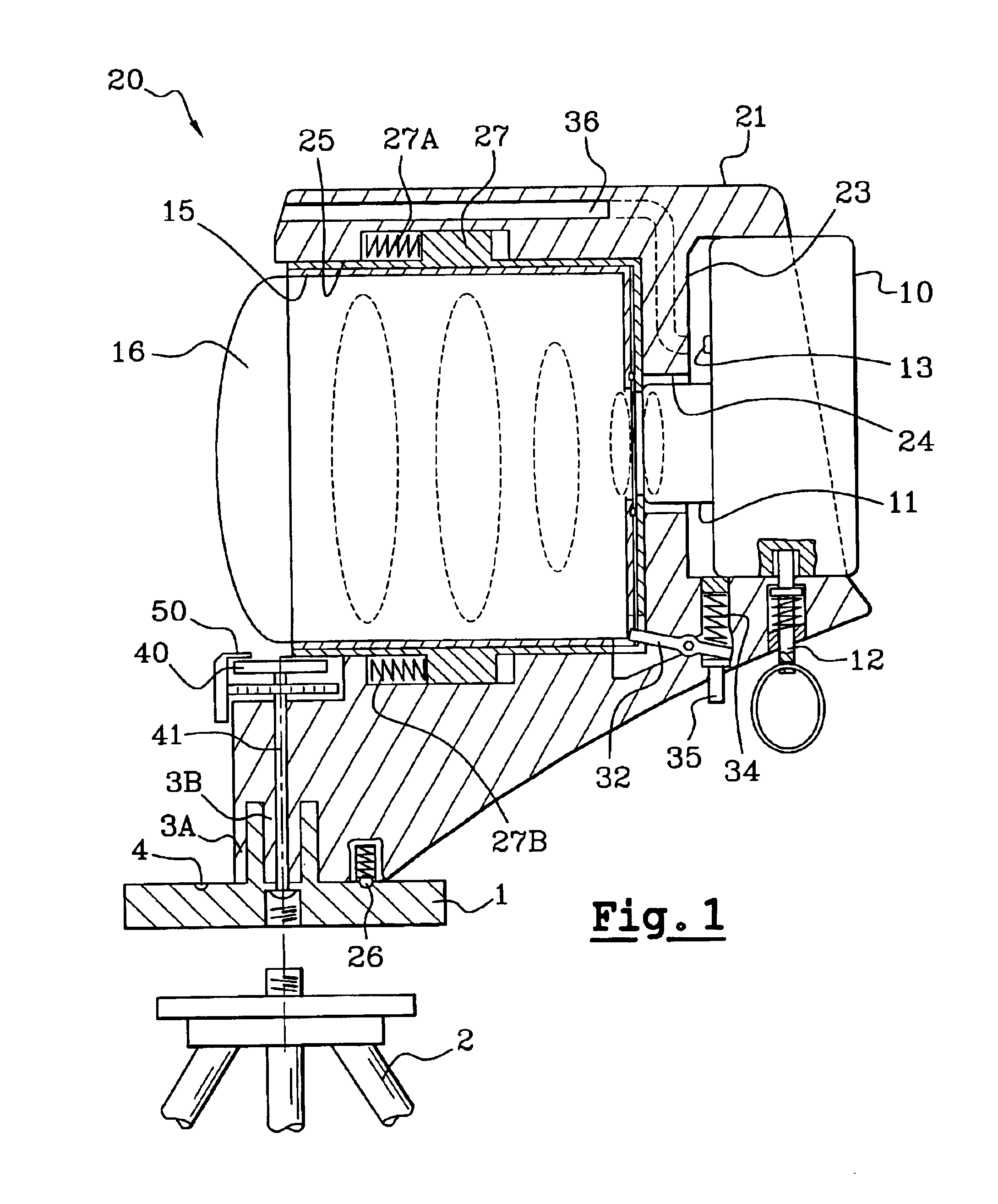
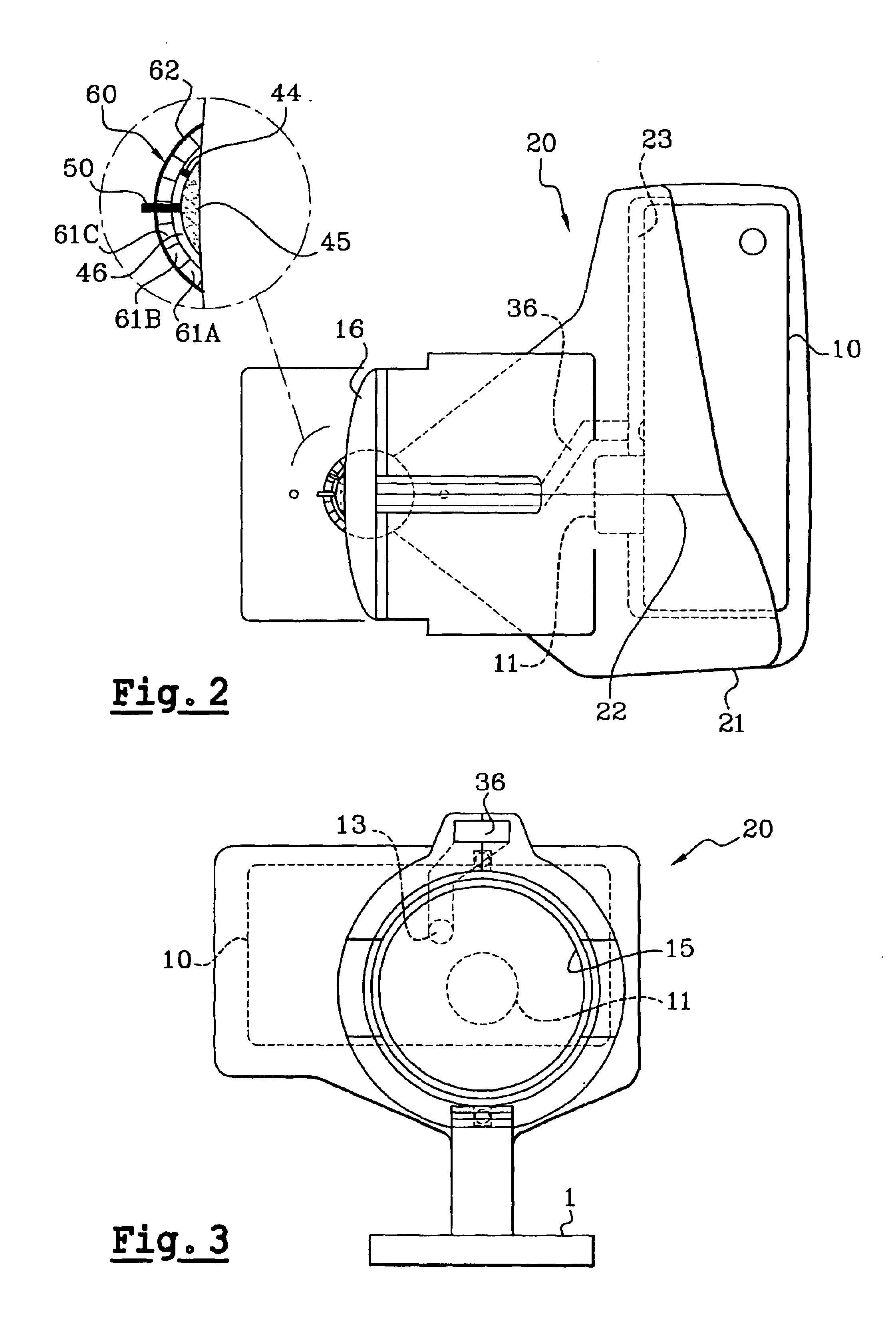
[0075]FIGS. 1 to 4 respectively represent by a cross-section, a top view, a front view and a perspective view one example of embodiment of a device 20 according to the present invention, intended to be used as a support for a compact camera and represented here with such a camera.

[0076]The support device 20 comprises a body 21 rotatably mounted on a base 1 attached to a tripod 2. The body 21 is produced here by welding or gluing two shells in moulded plastic, the assembly line 22 of the two components appearing in FIG. 4. With reference to FIG. 1, the back of the body 21 has a housing 23 receiving here a compact digital camera 10, comprising an irremovable or “fixed” lens 11. At the front of the housing 23 there is a cylindrical cavity 24 receiving the lens 11 and opening onto another cylindrical cavity 25 of a greater diameter, that opens onto the front ...


PUM


Abstract

A method for orienting a digital panoramic image obtained using at least one initial wide-angle image the image points of which are transferred into a three-dimensional coordinate system includes inserting an orientation mark into the initial image at the time of the exposure. The method further includes detecting the location of the orientation mark in the digital panoramic image, performed by an image analysis algorithm.

Description

CROSS-REFERENCE TO RELATED APPLICATIONS[0001]This application is a continuation of International Application No. PCT / FR02 / 00539, filed Feb. 13, 2002, and the disclosure of which is incorporated herein by reference.BACKGROUND OF THE INVENTION[0002]The present invention relates to digital photography and particularly to taking wide-angle photographs, as well as transforming wide-angle photographs into digital panoramic images.[0003]The present invention also relates to presenting digital panoramic images on a screen and virtual visits of places by means of panoramic images.[0004]In recent years, the fast progress of micro-computing and manufacturing techniques of digital cameras have led to a substantial development in digital photography and the access thereto by the public.[0005]Among the various applications offered by digital photography, the presentation of 360° panoramic images on computer screens has undergone a considerable boom as it is possible with this technique to produce...

Claims


Application Information

Patent Timeline
IPC IPC(8): G02B13/06G06T7/00H04N5/225
CPCG02B13/06G06T7/0018G06T7/0024H04N5/247H04N5/2251H04N5/23238G06T7/0042G06T7/80G06T7/30G06T7/73H04N23/50H04N23/698H04N23/90
Inventor ARTONNE, JEAN-CLAUDEMOUSTIER, CHRISTOPHE
Owner 6115187 CANADA
Learn More