Seismic monitoring and control method

Inactive Publication Date: 2005-04-26
GEO X SYST
View PDF20 Cites 66 Cited by
  • Summary
  • Abstract
  • Description
  • Claims
  • Application Information

AI Technical Summary

Benefits of technology

[0015]A preferred embodiment of the invention is a seismic communication system suitable to communicate information to a device at an underground location, including a seismic source to transmit information by the generation of a series of seismic shots at selected times, a seismic receiver at the underground target to receive the series of seismic shots, and a processor in communication with the seismic receiver to decipher the information based on measurement of times, the times being based on the timing of a reference shot. The time may be measured by the cross-correlation of a first seismic shot with a second seismic shot, and translated by use of a project menu correlating the intervals to pre-selected instructions. A downhole clock may also have its clock drift accounted for by the measurement of these interval lengths. One pr

Problems solved by technology

However, in many cases it is inconvenient or impractical to provide these physical linkages from the surface to the devices deep in the borehole.
However, this method is subject to limitations imposed by high-resistive rock formations and by deep boreholes.
Electromagnetic noise may also prevent successful communication.
Hardware in the wellbore such as casing strings and tubing may interfere with signal reception.
Deep boreholes imply high temperature and high pressure conditions, as well as requiring longer signal transmission distances and are not amenable to the application of existing electromagnetic communication systems.
This causes the shearing of a metal pin that initiates a chain of events resulting in firing of the gun.
However, this manipulation of borehole fluid pressure is time consuming, expensive, and sometimes hazardous.
Such high pressures induce significant stress to the downhole components.
This stress, along with the stress of very high temperatures, risks the overstress of a downhole tool.
This high wellhead pressure is a safety concern as it places great stress on the constraini

Method used


Image

  • Seismic monitoring and control method
  • Seismic monitoring and control method
  • Seismic monitoring and control method

Examples


Embodiment Construction

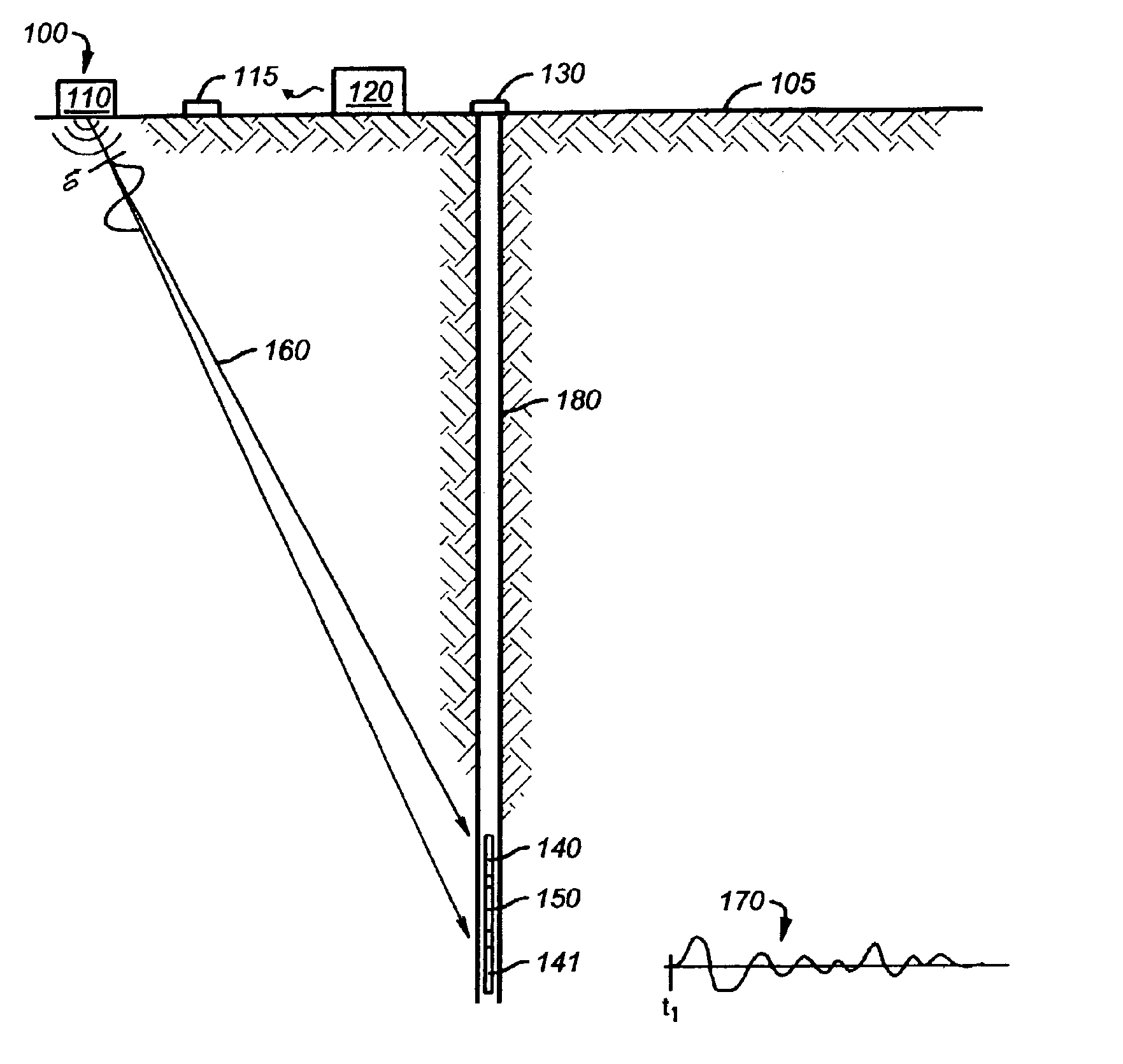
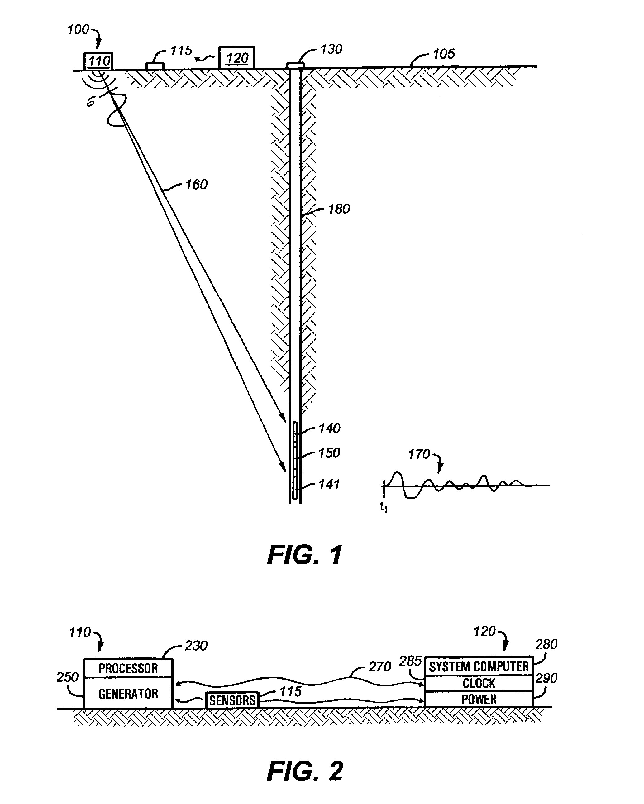
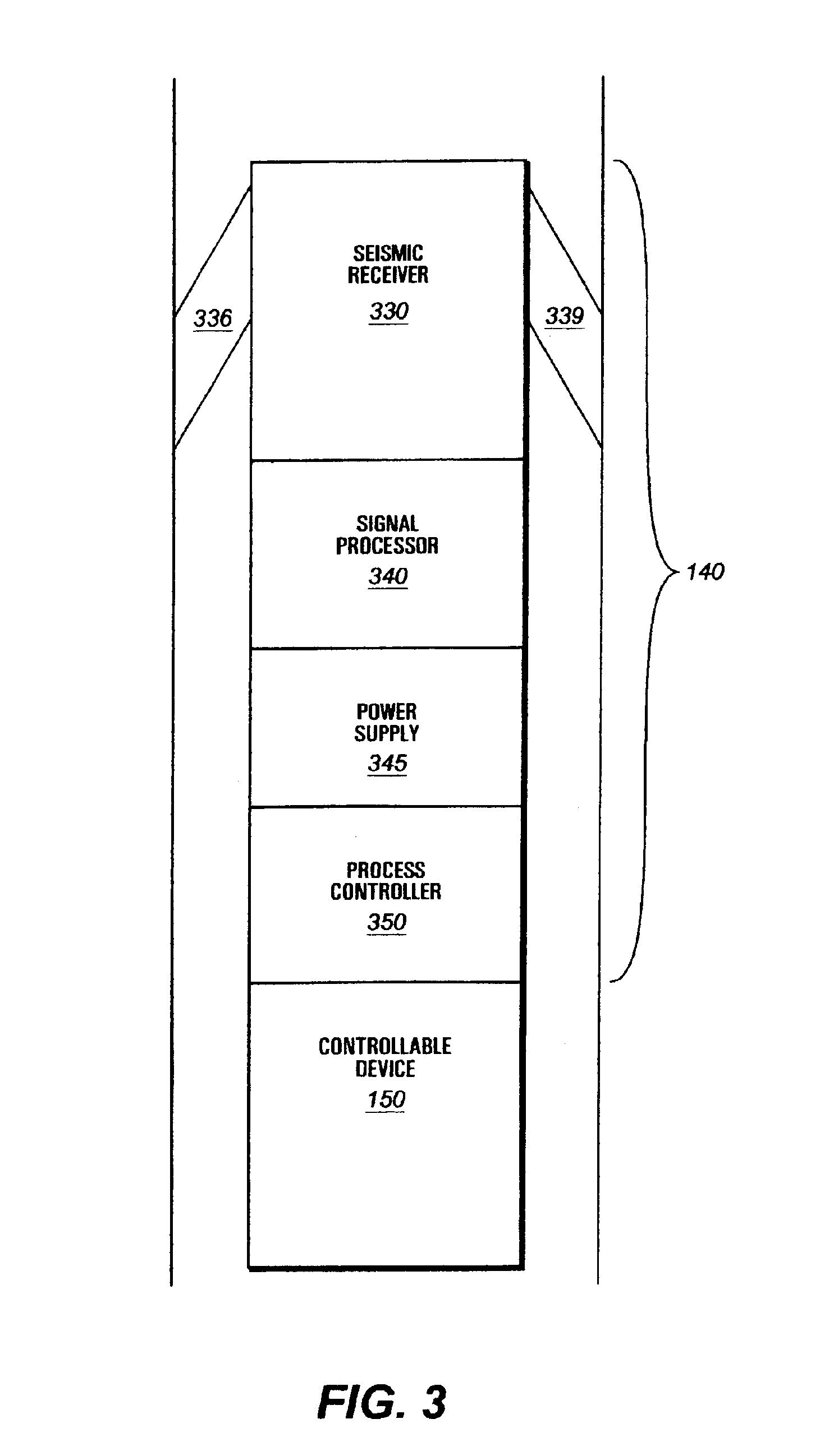
[0038]Throughout the description and claims to follow, the terms “shot”, “seismic shot”, “shot time”, “seismic source” and “shot point” shall be understood to be defined thus:[0039]SHOT: means a “seismic shot”; used interchangeably with “seismic shot”.[0040]SEISMIC SHOT: defined as (1) the deliberate act of creating seismic energy by a controlled seismic source at a source location in or on the earth; and (2) also is used to refer to the manifestations of that seismic energy as may be received and recorded at various locations away from the site of origin. For example, a “shot” may mean the received and digitized wave energy of the seismic shot as in “the shot was processed by cross-correlating with a prior shot.”[0041]SHOT TIME: defined as the time of initiation of the earliest seismic energy of the seismic shot.[0042]SHOT POINT: is the term used to denote the position of the seismic source when a seismic shot occurs.[0043]SEISMIC SOURCE: refers to the mechanism for creation of the...


PUM


Abstract

A seismic communication system suitable to communicate information to an underground device is disclosed. A seismic source (preferably on or near the surface of the earth) generates a timed series of seismic shots. These shots are then detected by one or more seismic receivers underground. Depending on the timing of these seismic shots, and the communication protocol selected, various information may be communicated to the underground target. Such a system is particularly desirable when the underground device includes a perforating gun because the perforating gun may not only be remotely detonated without the drawbacks of previous methods, but the detonation of the perforating gun charges may also be detected, giving an indication whether substantially fewer than all of the explosive charges detonated. The seismic communication system may also be used, as a component within a multi-functional well seismic system, for seismic reservoir monitoring or seismic monitoring of well operations.

Description

CROSS-REFERENCE TO RELATED APPLICATIONS[0001]This application is a Continuation-In-Part of U.S. patent application Ser. No. 09 / 595,384 filed Jun. 15, 2000 now U.S. Pat. No. 6,584,406.STATEMENT REGARDING FEDERALLY SPONSORED RESEARCH OR DEVELOPMENT[0002]Not Applicable.FIELD OF THE INVENTION[0003]The invention relates to subterranean well drilling, completion and maintenance. In particular, the invention is directed to seismic communication methods for controlling the operation of well tools.BACKGROUND OF THE INVENTION[0004]Those in the petroleum industry are particularly concerned with extracting petroleum from the earth by boring holes from the earth surface down into deep underground rock formations that contain petroleum. To evaluate the geologic conditions and to facilitate and control the extraction process, various mechanical devices are placed into the borehole. Often, these downhole devices must be remotely controlled from the surface. Controlling the actions of these mechanic...

Claims


Application Information

Patent Timeline
IPC IPC(8): E21B47/12E21B47/14G01V11/00
CPCG01V11/002E21B47/14
Inventor HARMON, JERALD L.BELL, WILLIAM T.
Owner GEO X SYST
Why Eureka
Try Eureka