NiAl-based approach for rocket combustion chambers

Inactive Publication Date: 2005-05-03
NASA
View PDF23 Cites 11 Cited by
  • Summary
  • Abstract
  • Description
  • Claims
  • Application Information

AI Technical Summary

Benefits of technology

[0025]According to another aspect of the invention, the first material is a NiAl-based alloy being selected to enhance a predetermined property such as environmental resistance, thermal conductivity and high temperature strength.
[0036]NiAl or NiAl-based alloys provide advantages over Ni-based superalloys in terms of weight, temperature capability, and environmental resistance as well as its higher thermal conductivity.

Problems solved by technology

However, NiAl alloys are not currently used in structural applications in actual engines because they are excessively brittle and are not damage tolerant.
Bimetallic concepts in jet engines have been considered in the past, but the time / temperature combinations typical of commercial jet aircraft engines are such that the bimetallic structures may degrade due to interdiffusion.
However, the molybdenum or molybdenum alloy is not innately resistant to oxidation at elevated temperatures.
Further, the reference does not provide for applications that involve exposure to hostile thermal environments.
None of the available art provides a bimetallic or multi-layered structural component for use in high heat flux and hostile thermal environments where each layer is structural, i.e. load-bearing, comprising at least about 20% of the structural thickness.

Method used


Image

  • NiAl-based approach for rocket combustion chambers
  • NiAl-based approach for rocket combustion chambers

Examples


Embodiment Construction

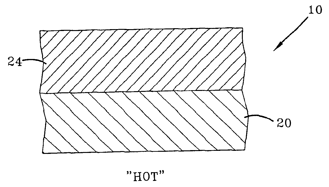
[0041]Referring now to the drawings wherein the showings are for purposes of illustrating a preferred embodiment of the invention only and not for purposes of limiting the same, FIG. 1 shows an exemplary rocket engine component 10. In a preferred embodiment, the component 10 can be, for example, the combustion chamber, throat and / or nozzle of a rocket engine.

[0042]Although the present invention is described with particular reference to a rocket engine component, the invention may be readily adapted to other components subjected to hostile thermal environments and high heat flux without departing from the spirit and scope of the invention.

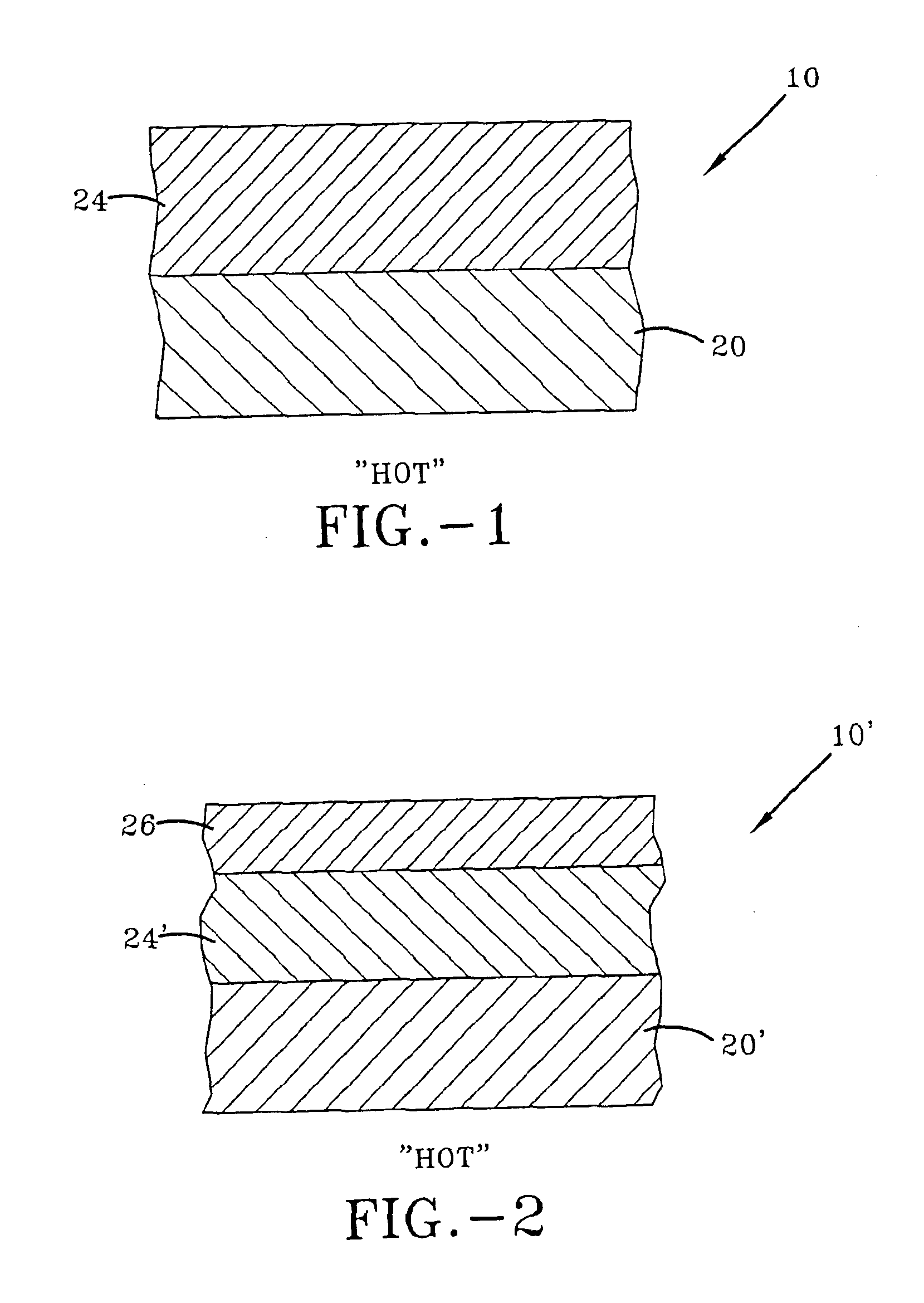
[0043]The component 10 includes an internal “hot side” which undergoes direct exposure to combustion gases such as hydrogen and oxygen. In the preferred embodiment, the body of component 10 is formed from two or more structural layers. The first structural layer 20 is adapted for exposure on the “hot side” of the component 10. In the present inventi...


PUM

PropertyMeasurementUnit
Lengthaaaaaaaaaa
Fractionaaaaaaaaaa
Percent by atomaaaaaaaaaa

Abstract

A multi-layered component, such as a rocket engine combustion chamber, includes NiAl or NiAl-based alloy as a structural layer on the “hot” side of the component. A second structural layer is formed of material selected from Ni-based superalloys, Co-based alloys, Fe-based alloys, Cu, and Cu-based alloys. The second material is more ductile than the NiAl and imparts increased toughness to the component. The second material is selected to enhance one or more predetermined physical properties of the component. Additional structural layers may be included with the additional material(s) being selected for their impact on physical properties of the component.

Description

[0001]This application is a continuation-in-part of application Ser. No. 10 / 105,110 filed Mar. 20, 2002, now abandoned.ORIGIN OF THE INVENTION[0002]The invention described herein was made by employees of the United States Government and may be manufactured and used by or for the Government for Government purposes without the payment of any royalties thereon or therefor.BACKGROUND OF THE INVENTION[0003]A. Field of Invention[0004]This invention pertains to the art of methods and apparatuses for providing components for use in hostile thermal environments. More particularly, the invention is directed to high heat flux devices having two or more structural layers.[0005]B. Description of the Related Art[0006]Current combustion chambers and related devices used in hydrogen-oxygen fueled rockets, or advanced air breathingcombined cycle” designs are placed in very high heat flux environments. As such, they are usually made out of copper alloys to take advantage of copper's high thermal co...

Claims


Application Information

Patent Timeline
IPC IPC(8): C23C28/02F02K9/68F02K9/00F02K9/62
CPCB32B15/01C23C28/021F02K9/62F02K9/68Y10T428/12944F05D2300/121F05D2300/506Y10T428/12937F05C2201/0466
Inventor NATHAL, MICHAEL V.GAYDA, JOHNNOEBE, RONALD D.
Owner NASA
Why Eureka
Try Eureka