
Car air-conditioning system

a technology for air conditioning systems and cars, applied in the direction of machines/engines, positive displacement liquid engines, lighting and heating apparatus, etc., to achieve the effect of effectively eliminating the adverse effect of operation and smoothly performing air conditioning

Inactive Publication Date: 2005-05-03
SANYO ELECTRIC CO LTD +2
View PDF21 Cites 64 Cited by
  • Summary
  • Abstract
  • Description
  • Claims
  • Application Information

AI Technical Summary

Benefits of technology

The present invention relates to an automotive air conditioning system that uses power generation means to charge a storage means and an electric compressor for the air conditioning system. The system includes control means that calculate the permissible power consumption and discharging current increments based on the permissible power generation and discharging current increments allowed in the power generation means and storage means. This allows for the increase in power consumption of the air conditioning system to remain within the range of the permissible power consumption and power generation increments. This prevents malfunctions or decreased performance of the air conditioning system due to low storage levels or full discharging of the storage means. The control means also consider the excess of the power consumption over the discharging current increment to maximize the air conditioning capability of the system.

Problems solved by technology

Particularly, the permissible discharging current increment in the storage means is also considered in the increase of power consumption of the air conditioning means in this condition.

Method used


Image

  • Car air-conditioning system
  • Car air-conditioning system
  • Car air-conditioning system

Examples


Embodiment Construction

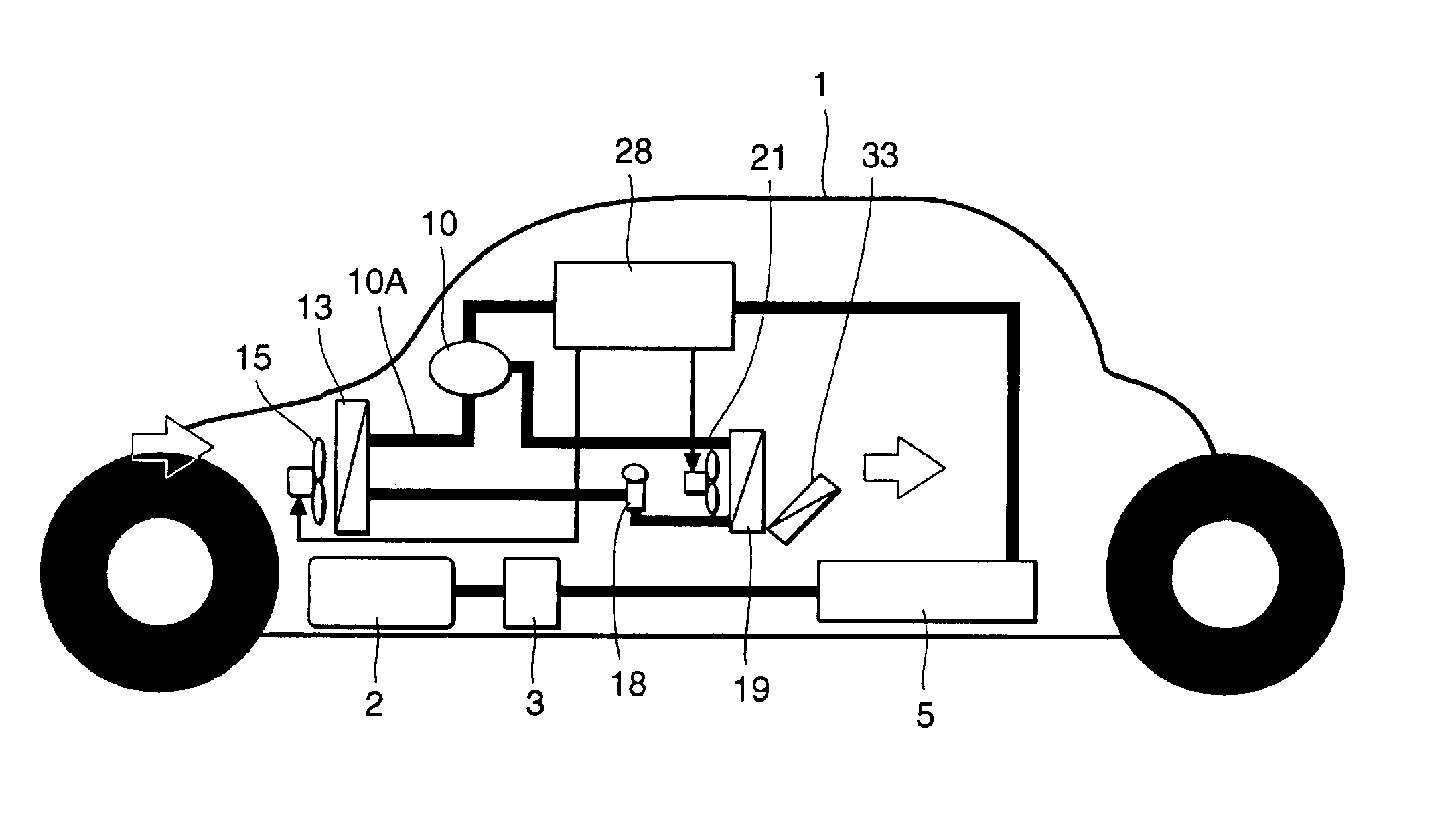
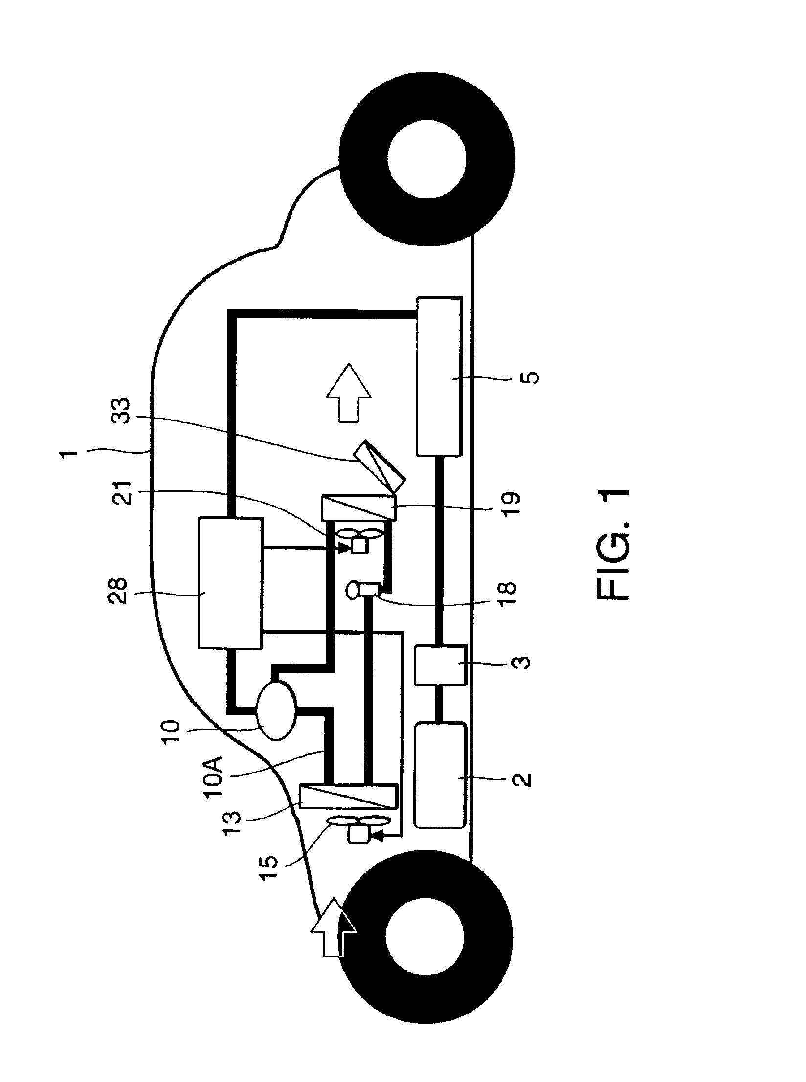
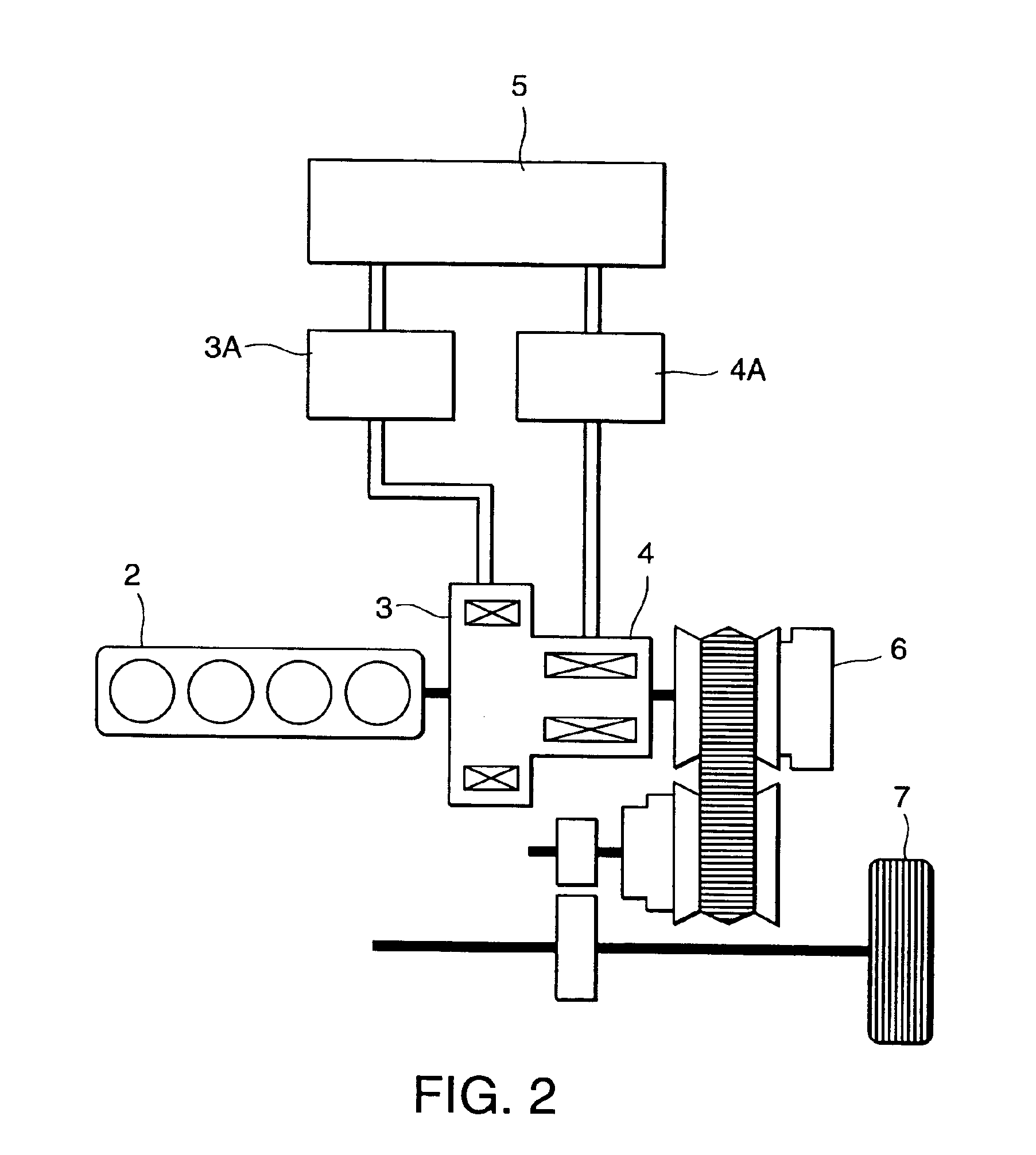
[0058]The preferred embodiments of the present invention will now be described in detail hereinafter with reference to the accompanying drawings. Referring to FIGS. 1, 2, 3, 4, and 5, there are shown a constitutional diagram of an automobile 1 as an embodiment to which is applied an automotive air conditioning system of the present invention, a constitutional diagram of a driving system of the automobile shown in FIG. 1, a constitutional diagram of an air conditioning unit (AC) as air conditioning means in the present invention, a refrigerant circuit diagram of the air conditioning unit 9, and a block diagram of a control system of the automobile 1 including the automotive air conditioning system of the present invention, respectively.

[0059]In respective diagrams, the automobile 1 in the embodiment is a hybrid vehicle (HEV) set forth in the above, and there are mounted an engine (an internal combustion engine) 2 and an air conditioning unit (air conditioning means) 9 including an ai...


PUM


Abstract

There is provided an automotive air conditioning system, which is free from troubles in traveling itself caused by power consumption in air conditioning means in an automobile having storage means, power generation means for charging the storage means, and air conditioning means having an electric compressor driven by feeding from the storage means. Control means calculates a permissible power consumption increment in the air conditioning means by adding a permissible power generation increment to a permissible discharging current increment on tha basis of the permissible power generation increment allowable in the power generation means and the permissible discharging current increment allowable in the storage means to increase power consumption of the air conditioning means within the range of the permissible power consumption increment and to increase power generation of the power generation means within the range of the permissible power generation increment according to an increment of power consumption of the air conditioning means.

Description

BACKGROUND OF THE INVENTION[0001]1. Field of the Invention[0002]The present invention relates to an automotive air conditioning system for use in an automobile having storage means, power generation means for charging the storage means, and air conditioning means having an electric compressor driven by feeding from the storage means.[0003]2. Related Background Art[0004]Conventionally, a car air-conditioner (air conditioning means) for use in a general automobile has had a compressor driven by a fuel engine (an internal combustion engine). High-temperature gas refrigerant, which has been discharged from the compressor and flowed into an exterior unit heat exchanger, radiates heat through heat exchanges with an air outside the passenger compartment caused by an exterior unit blower and is condensed to a liquid. Thereafter it flows into an interior unit heat exchanger arranged inside the passenger compartment via an expansion valve. The liquid refrigerant evaporates there and absorbs h...

Claims


Application Information

Patent Timeline
Patent Type & Authority Patents(United States)
IPC IPC(8): B60H1/32B60H1/00F04B49/00F04B49/10
CPCB60H1/00385B60H1/3208B60H1/3222B60H2001/3273B60H2001/3266B60H1/32
Inventor KUBO, MAMORUSASAKI, SHIGEHARUOTAGAKI, KAZUHISATAKAGI, SUSUMUWATANABE, KENZO
Owner SANYO ELECTRIC CO LTD
Learn More