Tactile sensor and gripping robot using the same

a technology of tactile sensor and gripping robot, which is applied in the direction of force measurement, instruments, force/torque/work measurement apparatus, etc., can solve the problems of unsuitable small force detection with high accuracy, and the sensor is difficult to attach the sensor to the surface of the skin or the fingertip, so as to reduce mutual interference, improve detection accuracy, and be easy to bend

Active Publication Date: 2005-05-03
TOSHIBA ELECTRIC ENG +2
View PDF9 Cites 49 Cited by
  • Summary
  • Abstract
  • Description
  • Claims
  • Application Information

AI Technical Summary

Benefits of technology

[0013]With the first strain gauge attached to the first strain generating section, the force (pressure) in the Z direction (vertical direction to the attachment surface) is detected, and with the second to fifth strain gauges respectively attached to the second to fifth strain generating sections supporting the first strain generating section, the forces (pressures) in the X direction and Y direction (parallel direction to the attachment surface (searing direction), respectively) are detected. Each strain generating section has a planer shape being easily bent, so that the detection can be performed from small force. Further, it is possible to improve detection accuracy for example by providing dedicated strain gauges for detecting the forces in respective directions, which serves to reduce mutual interference.
[0014]Further, another tactile sensor according to the present invention has the tactile sensors as elements aligned in an array. The tactile sensors as elements can be fabricated minutely for example by punching and bending of a plate material, so that it is easily possible to align them in an array. By adopting an array structure, a certain attachment area can be ensured as a tactile sensor. Backed by this, the detection of contact pressure in an attachment surface can be made more accurately.
[0015]Furthermore, a gripping robot according to the present invention includes the tactile sensor having the array structure for detecting contact pressure. The tactile sensor having the array structure can cover a certain area when attached and can be attached so as to comply with a rounded attachment surface. Accordingly, by attaching the tactile sensor for example to a fingertip, the gripping robot can perform desirable contact pressure detection with the help of the detection capability of the three component forces with high accuracy from small force.

Problems solved by technology

It is therefore impossible to attach the sensor to a surface of a skin or a fingertip because of the structure.
In addition, it is considered that the sensor is unsuitable to detect small force with high accuracy due to the rigid body used therein.[Patent document 1] JP-A 8-323678[Patent document 2] JP-A 2002-181640[Patent document 3] JP-A 2000-266620

Method used


Image

  • Tactile sensor and gripping robot using the same
  • Tactile sensor and gripping robot using the same
  • Tactile sensor and gripping robot using the same

Examples


first example

[First Example]

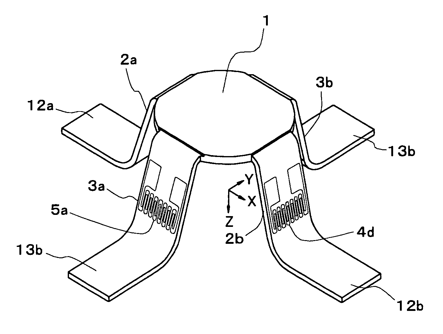
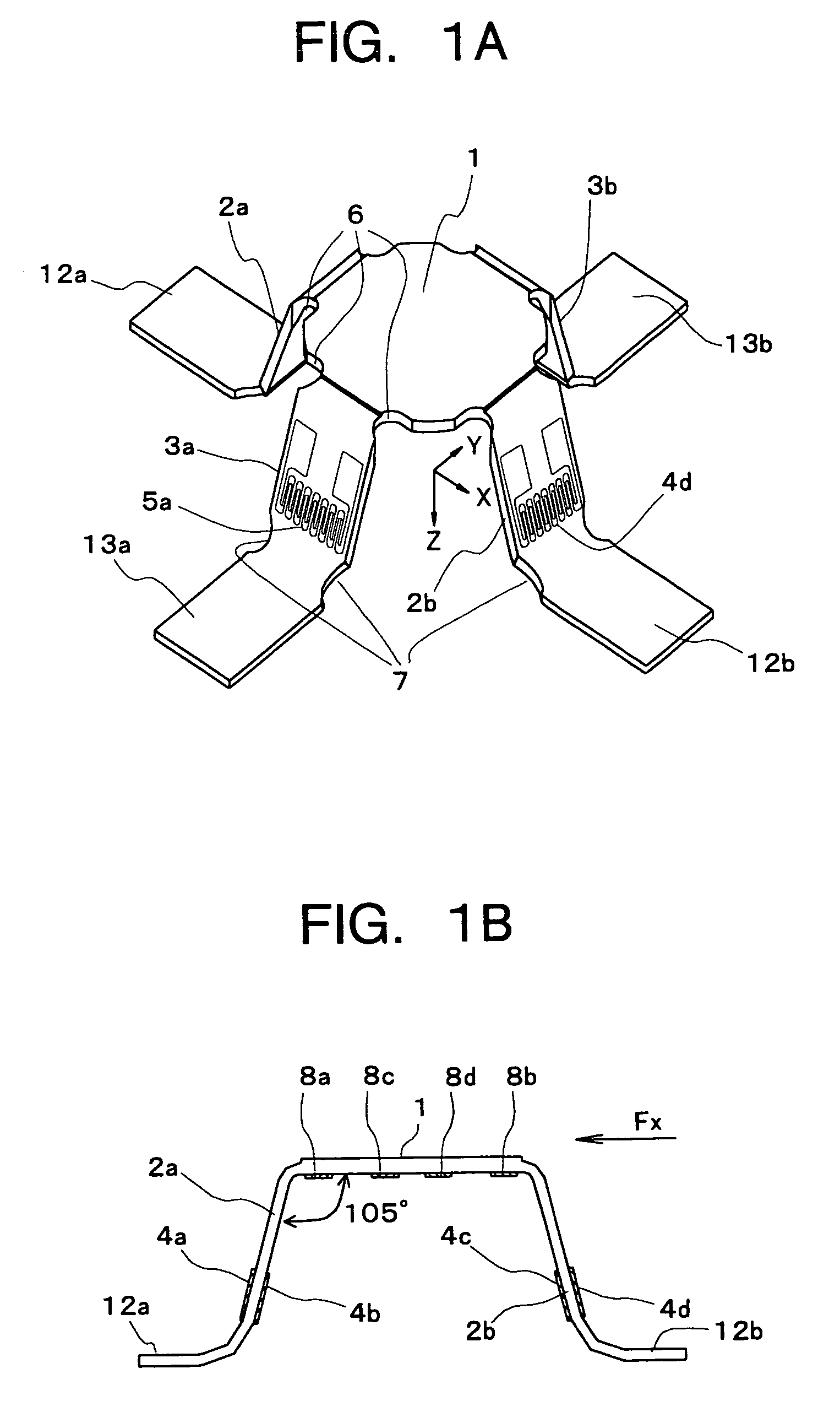
[0059]Hereinbelow, examples will be described. As a first example, a tactile sensor is formed by punching a metal plate having a thickness of 0.1 mm into a cross shape using a press and by bending it so as to leave a center planer portion as shown in FIG. 1. The height of the tactile sensor is set to 1.6 mm.

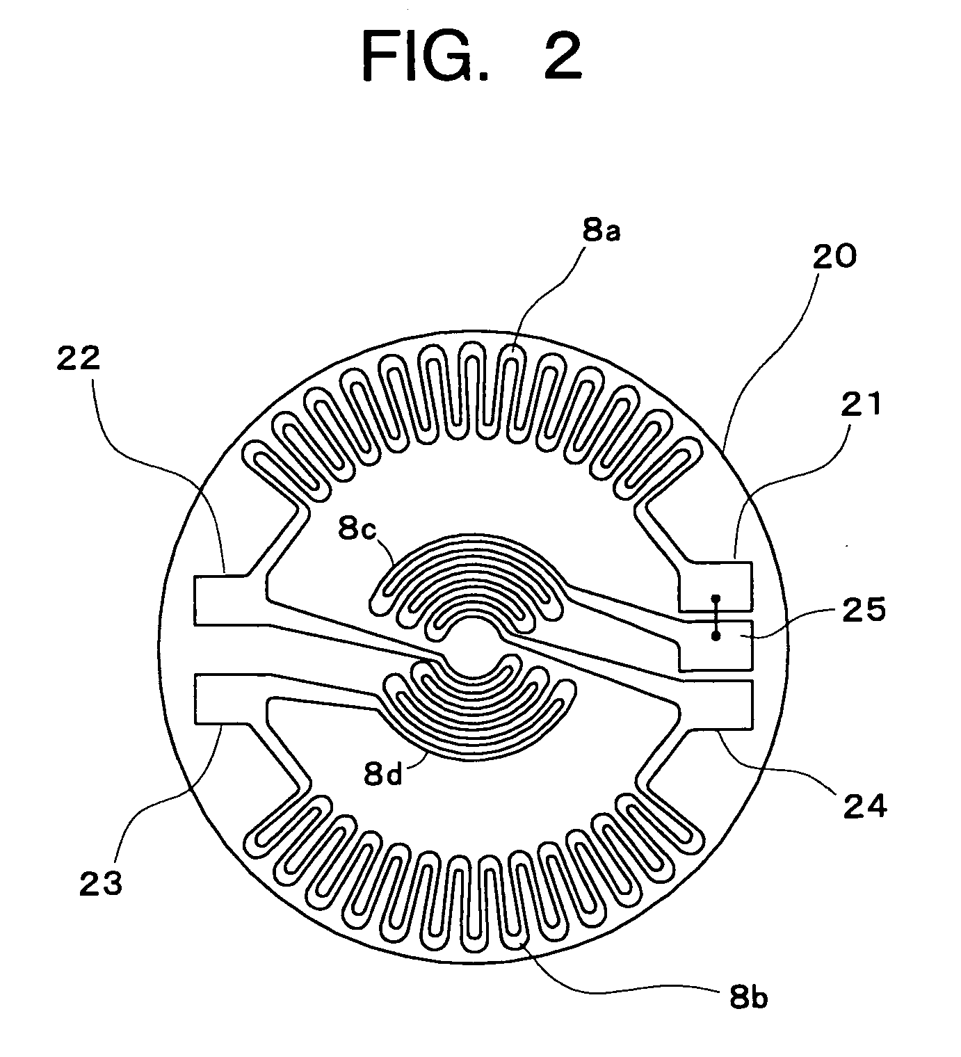
[0060]The input voltage into a bridge circuit by strain gauges 4a, 4b, 4c, 4d (5a, . . . ) is set to 5V. The nominal resistance values of the strain gauges 4a, 4b, 4c, 4d (5a, . . . ) are 350 Ω, respectively. After fixing undersurfaces of four foot sections 12a, 12b. 13a, 13b

of the tactile sensor to an attachment surface, a force Fx=250 g is applied in the X direction. The evaluation items are three: output voltage of a bridge circuit, interference between a detection of Fx and a detection of Fy, and nonlinearity in Fx detection.

[0061]As a result obtained from the above, the output voltage of the bridge circuit was 1.7 mV to 1.8 mV, the interference between the de...

second example

[Second Example]

[0062]In a second example, strain gauges are attached only to single sides of strain generating sections 2a, 2b, 3a, 3b (only outside strain gauge 4a, 4d, 5a, . . . are attached), and the same structure as of the first example is adopted for the other structure. This structure is shown in FIG. 5A and FIG. 5B. FIG. 5A and FIG. 5B are views schematically showing the structure of the tactile sensor of another embodiment according to the present invention and the same reference numerals will be used to designate the corresponding components as those already described in the above.

[0063]A bridge circuit composed of strain gauges 4a, 4b is configured by replacing the strain gauges 4b, 4c in the bridge circuit shown in FIG. 4B with external fixed resistors. At the time, as in the case of the first example, a force Fx=250 g is applied in the X direction. As a result obtained from the above, the output voltage of the bridge circuit was 0.85 mV to 0.9 mV, the interference bet...

third example

[Third Example]

[0064]In a third example, no recessed portion is provided in the vicinity of boundaries between a strain generating section 1 and strain generating sections 2a, 2b, 3a, 3b, which are four legs, and in the vicinity of boundaries between the strain generating sections 2a, 2b, 3a, 3b and foot sections 12a, 12b, 13a, 13b. The other structure is the same as of the first example. This structure is shown in FIG. 6A and FIG. 6B. FIG. 6A and FIG. 6B are views schematically showing the structure of the tactile sensor of still another embodiment according to the present invention and the same reference numerals will be used to designate the corresponding components as those already described in the above.

[0065]As in the case of the first example, a force Fx=250 g is applied. As a result obtained from the above, the output voltage of the bridge circuit was 0.5 mV to 0.55 mV, the interference between the detection of Fx and the detection of Fy was 30% or below, and the nonlineari...


PUM

PropertyMeasurementUnit
angleaaaaaaaaaa
angleaaaaaaaaaa
angleaaaaaaaaaa

Abstract

Disclosed is a tactile sensor which includes: a disk-shaped first strain generating section; plate-shaped second to fifth strain generating sections each provided as an extension of the first strain generating section extended from one of four substantially equiangular peripheral edge portions of the first strain generating section, each of the second to fifth strain generating sections being structured to support the first strain generating section as a leg thereof; first to fourth foot sections extended at a side different from a first strain generating section side respectively from the second to fifth strain generating sections; a diaphragm type first strain gauge attached to a discoid surface of the first strain generating section; and second to fifth strain gauges attached respectively to planer surfaces of the second to fifth strain generating sections, and a gripping robot using the tactile sensor for detecting contact pressure.

Description

BACKGROUND[0001]1. Field of the Invention[0002]The present invention relates to a tactile sensor that detects force (pressure) applied to an attachment surface and a gripping robot using the tactile sensor that detects contact pressure, and more specifically, to the tactile sensor suitable for detecting three component forces (in the X direction, Y direction, and Z direction) with high accuracy from small force and the gripping robot using the same.[0003]2. Description of the Related Art[0004]As a tactile sensor of the kind attachable to a fingertip, there is one used in a “soft object grip device” disclosed in Japanese Patent Laid-Open Application No. Hei 8-323678, as an example. This sensor detects contact areas with a lot of minute ON / OFF switches provided therein. The sensor is intended to realize optimal gripping of an object by recognizing size and flexibility of the object from the relation between the detected contact areas and distances between fingertips. The sensor princi...

Claims


Application Information

Patent Timeline
Patent Type & Authority Patents(United States)
IPC IPC(8): B25J13/08G01L5/22G01L5/16
CPCB25J13/084G01L5/228G01L5/226G01L5/161G01L5/1627
Inventor KUROGI, SHIRONOJIRI, YOSHIRONEMOTO, YUJIHIRAMA, NAOMICHITSUJIUCHI, NOBUTAKAKOKETSU, KAZUMITSUTIYA, YOTARO
Owner TOSHIBA ELECTRIC ENG
Why Eureka
Try Eureka