Engine control device for water vehicle

Inactive Publication Date: 2005-05-03
YAMAHA MARINE KK
View PDF16 Cites 35 Cited by
  • Summary
  • Abstract
  • Description
  • Claims
  • Application Information

AI Technical Summary

Benefits of technology

[0010]In accordance with another embodiment of at least one of the inventions disclosed herein, a method of regulating the output of an engine comprises receiving engine output requests between minimum and maximum magnitudes, controlling a flow of air into a combustion chamber of the engine in accordance with the engine output requests and, in a first mode, allowing a maximum amount of air to flow to the combustion chamber in response to a maximum magnitude engine output request. In a second mode, the method includes preventing the maximum amount of air from flowing to the combustion chamber in response to a maximum magnitude engine output request.

Problems solved by technology

Operating a watercraft in such a manner can cause some discomfort.

Method used


Image

  • Engine control device for water vehicle
  • Engine control device for water vehicle
  • Engine control device for water vehicle

Examples


Embodiment Construction

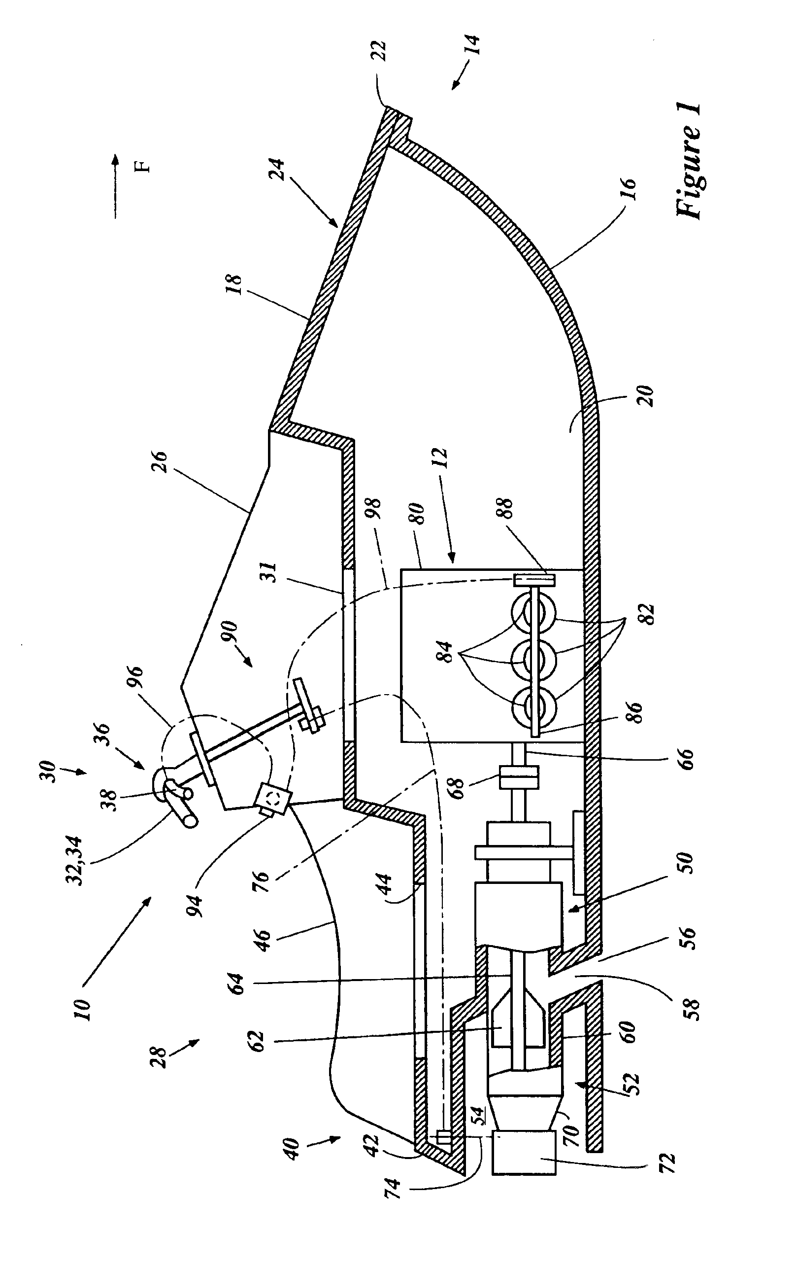
[0019]With reference to FIGS. 1 and 2, an overall description of a personal watercraft 10 is set forth below. An arrow F shown in FIG. 1 indicates a forward direction of travel of the watercraft 10.

[0020]The watercraft 10 includes an engine 12 in the hull 14. The hull 14 includes a lower hull section 16 and an upper deck section 18. Both of the hull sections 16, 18 may be constructed of, for example, a molded fiberglass reinforced resin or a sheet molding compound. The hull sections 16, 18 may, however, be constructed from a variety of other materials selected to make the watercraft lightweight and buoyant. The lower hull section 16 and the upper hull section 18 are coupled together to define an internal cavity 20. The hull sections 16, 18 are coupled together along a bond flange 22.

[0021]The hull 14 extends longitudinally and thereby generally defines a longitudinal axis (not shown). Along the longitudinal axis, from a forward portion of the watercraft 10 to a rearward portion, the...


PUM


Abstract

A watercraft includes an engine output control device that can adjust the maximum output of the engine. The output device can be constructed of mechanical devices for adjusting the relationship between the movement of a throttle lever and a throttle valve, an electronic device for proportionally controlling the position of throttle valves in relation to the movement of the throttle lever, are other devices for controlling engine speeds in other ways.

Description

PRIORITY INFORMATION[0001]This application is based on Japanese Patent Application No. 2001-263768, filed Aug. 31, 2001, and is also based on and claims priority to Japanese Patent Application No. 2002-020047 filed Jan. 29, 2002, the entire contents of both of which are hereby expressly incorporated by reference.BACKGROUND OF THE INVENTION[0002]1. Field of the Invention[0003]The present invention generally relates to a control device for an engine. More specifically, the present invention relates to an engine power output control device for the engine of the watercraft.[0004]2. Description of the Related Art[0005]As personal watercraft have become popular, they have become increasingly fast. Today, certain personal watercrafts are capable of speeds greater than 60 miles per hour. To attain such speeds, these personal watercrafts are driven by high power output motors.[0006]Typically, two-cycle engines are used in personal watercraft because two-cycle engines have a fairly high power...

Claims


Application Information

Patent Timeline
Patent Type & Authority Patents(United States)
IPC IPC(8): B63H21/00B63H21/22F02B61/04F02B61/00F02D11/10F02D11/02F02D11/00B63B35/73
CPCB63H21/213F02B61/045F02D11/105F02D11/02B63B35/731B63H21/24F05C2201/021F02D2011/103F02D2200/0404F02D2200/602B63B34/10
Inventor SUZUKI, AKITAKAMINEO, SHIGEHARUMOTOSE, HITOSHI
Owner YAMAHA MARINE KK
Why Eureka
Try Eureka