
Conveying apparatus, inspecting apparatus and aligningly and supplying apparatus

Inactive Publication Date: 2005-05-03
DAIICHI JITSUGYO VISWILL
View PDF15 Cites 8 Cited by
  • Summary
  • Abstract
  • Description
  • Claims
  • Application Information

AI Technical Summary

Benefits of technology

[0013]In accordance with the conveying apparatus described in the first aspect of the present invention, since the apparatus includes the rotary disc portion and the linear conveying portion, it is possible to stably convey without requiring a lot of space even when the linear conveying portion is arranged horizontally, and further it is possible to execute a side surface inspection of the conveyed article conveyed in the rotary disc.
[0015]In accordance with the conveying apparatus described in the second aspect of the present invention, in addition to the same effect as that of the first aspect, it is possible to fix the supporting member to the peripheral edge of the rotary disc portion being different from the conveying belt in the linear conveying portion and it is possible to make a cross sectional area of the supporting member small, so that it is possible to stably inspect the conveyed article without working against the side surface inspection of the conveyed article and without slipping the conveyed article. In particular, when the supporting member is constituted by a structure having a buffering property and an adhesive property, for example, an O-ring, it is possible to convey at a high speed and stably.
[0017]In accordance with the conveying apparatus described in the third aspect, in addition to the same effect as that of the second aspect, it is possible to inspect both the front and back surfaces of the conveyed article by the linear conveying portion.
[0019]In accordance with the conveying apparatus described in the fourth aspect, in addition to the same effect as that of the third aspect, it is possible to shut the air of the slit requiring no suction in the rotary disc. Accordingly, it is possible to save the amount of air suctioning, the capacity of air blower and the amount of energy used.
[0021]In accordance with the inspecting apparatus described in the fifth aspect, in addition to the same effects as that of the first aspect, the second aspect, the third aspect or the fourth aspect, it is possible to inspect the side surface and both the front and back surfaces of the conveyed article, and it is possible to sort in response to an inspected result.
[0023]In accordance with the aligning and supplying apparatus described in the sixth aspect, it is possible to align all the small articles having the different width and thickness and stabilizing under the turned state in a low attitude, and it is not necessary to sort, so that it is possible to improve a processing efficiency.

Problems solved by technology

However, this requires a lot of space to accommodate the linear conveying apparatuses.
As such, a conveyed article held by suctioning sometimes vibrates more a higher elevations and this makes it difficult to properly inspect these articles.
If the diameter of the belts increase and a small article is conveyed, the side surfaces of these articles cannot be properly inspected because the side surfaces are covered by the belts.
The contact portion has a low coefficient of friction which causes the article to slip, whereby the conveying of the article is easily displaced by its own weight.
However, since the rotary tube shaft is provided, the air is unnecessarily sucked from the slit corresponding to a portion requiring no suction.
Accordingly, a processing efficiency is significantly deteriorated.

Method used


Image

  • Conveying apparatus, inspecting apparatus and aligningly and supplying apparatus
  • Conveying apparatus, inspecting apparatus and aligningly and supplying apparatus
  • Conveying apparatus, inspecting apparatus and aligningly and supplying apparatus

Examples


Embodiment Construction

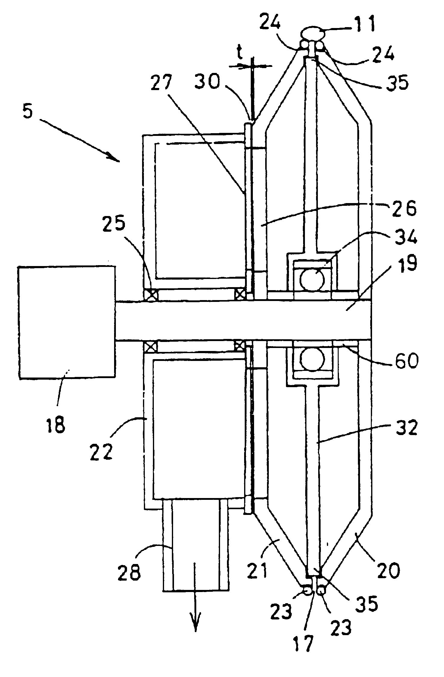
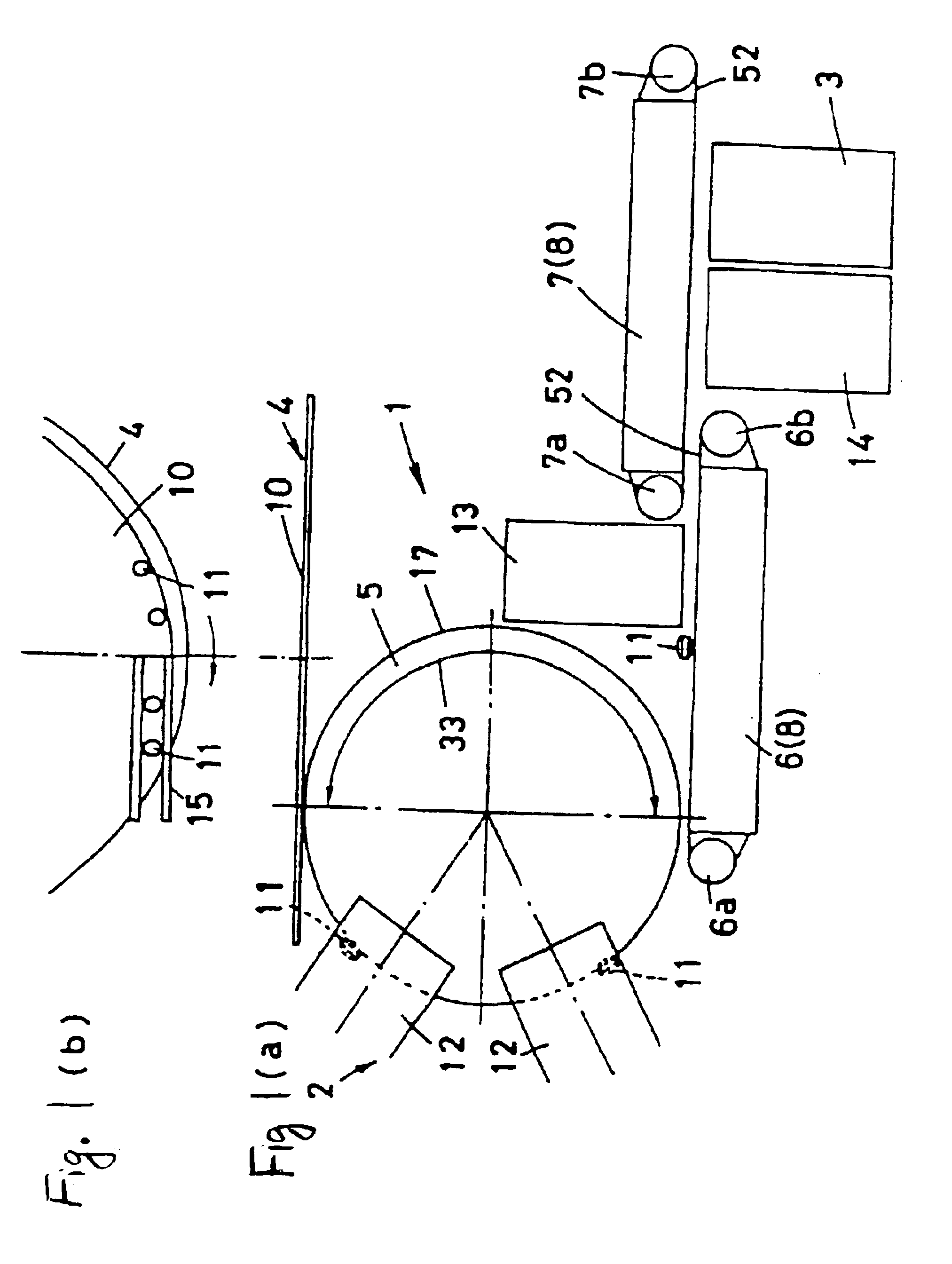
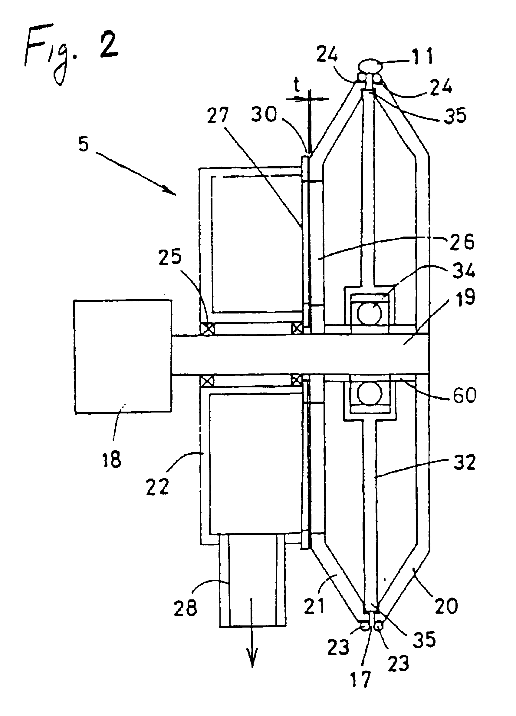
[0038]A description will be given of an embodiment in accordance with the present invention with reference to FIGS. 1 to 10. FIG. 1 shows an inspecting apparatus, which has a conveying apparatus 1, an inspection portion 2 and a sorting portion 3. The conveying apparatus 1 has an aligning and supplying apparatus 4, a rotary disc portion 5, a first conveying portion 6 and a second conveying portion 7. The first conveying portion 6 and the second conveying portion 7 form a linear conveying portion 8. The aligning and supplying apparatus 4 is structured such that a conveyed article 11, for example, a small article, in this case, a tablet revolves around a turn table 10. The conveyed article 11 is aligned along a peripheral edge portion of the turn table 10 by an aligning guide (not shown). The article is linearly fed by a width guide 15 (mentioned below) arranged near the peripheral edge portion of the turn table 10 with a slight gap so as to be supplied to the rotary disc portion 5.

[00...


PUM


Abstract

A conveying apparatus is provided with a rotary disc portion with a suction means which forms a slit on an outer peripheral surface and sucks through the slit so as to convey a conveyed article in a state of holding the conveyed article by suction to both sides of the slit, and a linear conveying portion with a suction means which sucks the conveyed article riding over a pair of parallel conveying belts through a gap between the conveying belts so as to convey the conveyed article in a state of holding the conveyed article by suction to the conveying belt, and has one end opposing to the outer peripheral surface of the rotary disc portion so as to be capable of transfer the conveyed article. The conveying apparatus of the invention, the inspecting apparatus and an aligning and supplying apparatus allow for execution of a side surface inspection of a small article stably without requiring a lot of space.

Description

BACKGROUND OF THE INVENTION[0001]1. Technical Field[0002]The present invention relates to a conveying apparatus for an article to be inspected by an inspecting apparatus for small articles such as medicine in the form of tablets, capsules, etc., small confectionery such as a candy and the like, a washer, a battery cell, or the like, in a defect inspection process, a visual inspection process, a dimensional check process or the like.[0003]2. Background Art[0004]When inspecting surfaces of articles such as the small articles conveyed using a conveying apparatus, a plurality of conveying apparatuses formed in a linear direction have been conventionally arranged in series so as to easily transfer the article from one conveying apparatus to another conveying apparatus. However, this requires a lot of space to accommodate the linear conveying apparatuses. Alternatively, when positioning the conveying apparatus in a vertical direction, the linear space required to accommodate the apparatus...

Claims


Application Information

Patent Timeline
IPC IPC(8): B65G47/14B65G15/58B65G47/86B65G15/12
CPCB65G47/1485
Inventor KAKIUCHI, SHOGOTSUTSUMI, KOJI
Owner DAIICHI JITSUGYO VISWILL
Learn More