Female and male couplers of pipe coupling

a female and male coupler technology, applied in the field of pipe couplings, can solve the problems of increasing resistance, complex operation inability to meet the needs of valve support members, so as to achieve the effect of greatly reducing the resistance of passag

Active Publication Date: 2005-05-03
NITTO KOHKI CO LTD
View PDF16 Cites 76 Cited by
  • Summary
  • Abstract
  • Description
  • Claims
  • Application Information

AI Technical Summary

Benefits of technology

[0013]Thus, in each of the female coupler and the male coupler of the pipe coupling according to the present invention, a valve support ring is provided that has an outer diameter which is smaller than that of the cylindrical connecting portion, thereby ensuring that sufficient space exists between the valve support ring and the fluid passage wall surface of the female coupler body or the male coupler body. In addition, the support legs are connected to the valve support ring at the rear end surface thereof. Therefore, the support legs do not obstruct the space. Accordingly, relative to the conventional arrangement, passage resistance can be greatly reduced.

Problems solved by technology

In conventional female and male couplers, however, preparation and fitting of valve support members requires complicated operations to be carried out.
Therefore, a problem arises in the conventional female and male couplers that a cross-sectional area of their respective fluid passages is caused to become narrow, resulting in an increase in resistance therein.
However, production of this type of male and female coupler is complicated and is therefore impractical.
It is also necessary to provide at the distal end of the through-hole a valve seat having a small diameter, which makes it difficult to form the hole in the female coupler body.

Method used


Image

  • Female and male couplers of pipe coupling
  • Female and male couplers of pipe coupling
  • Female and male couplers of pipe coupling

Examples


Embodiment Construction

[0027]Embodiments of the female and male couplers of a pipe coupling according to the present invention will be described below with reference to the accompanying drawings.

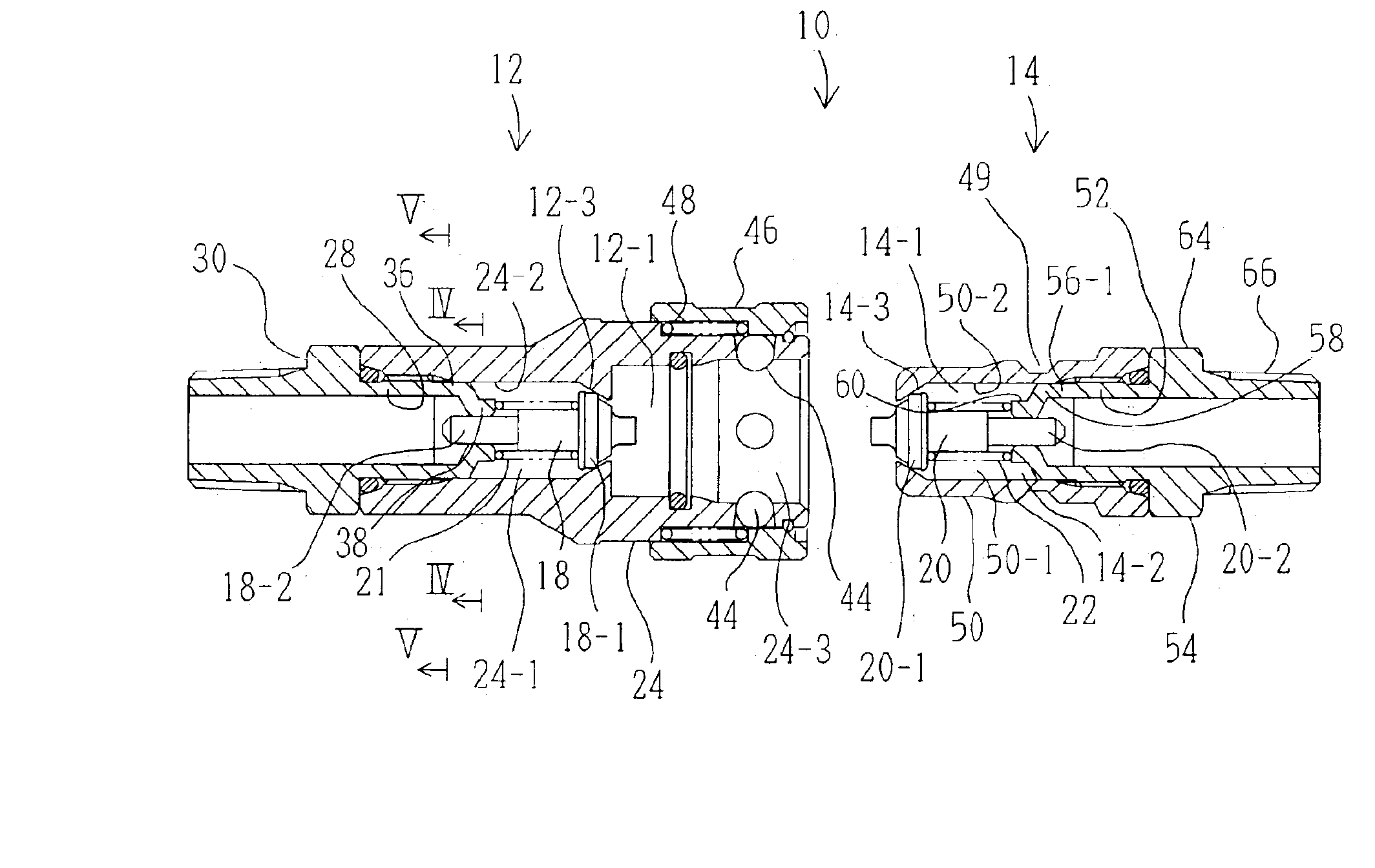
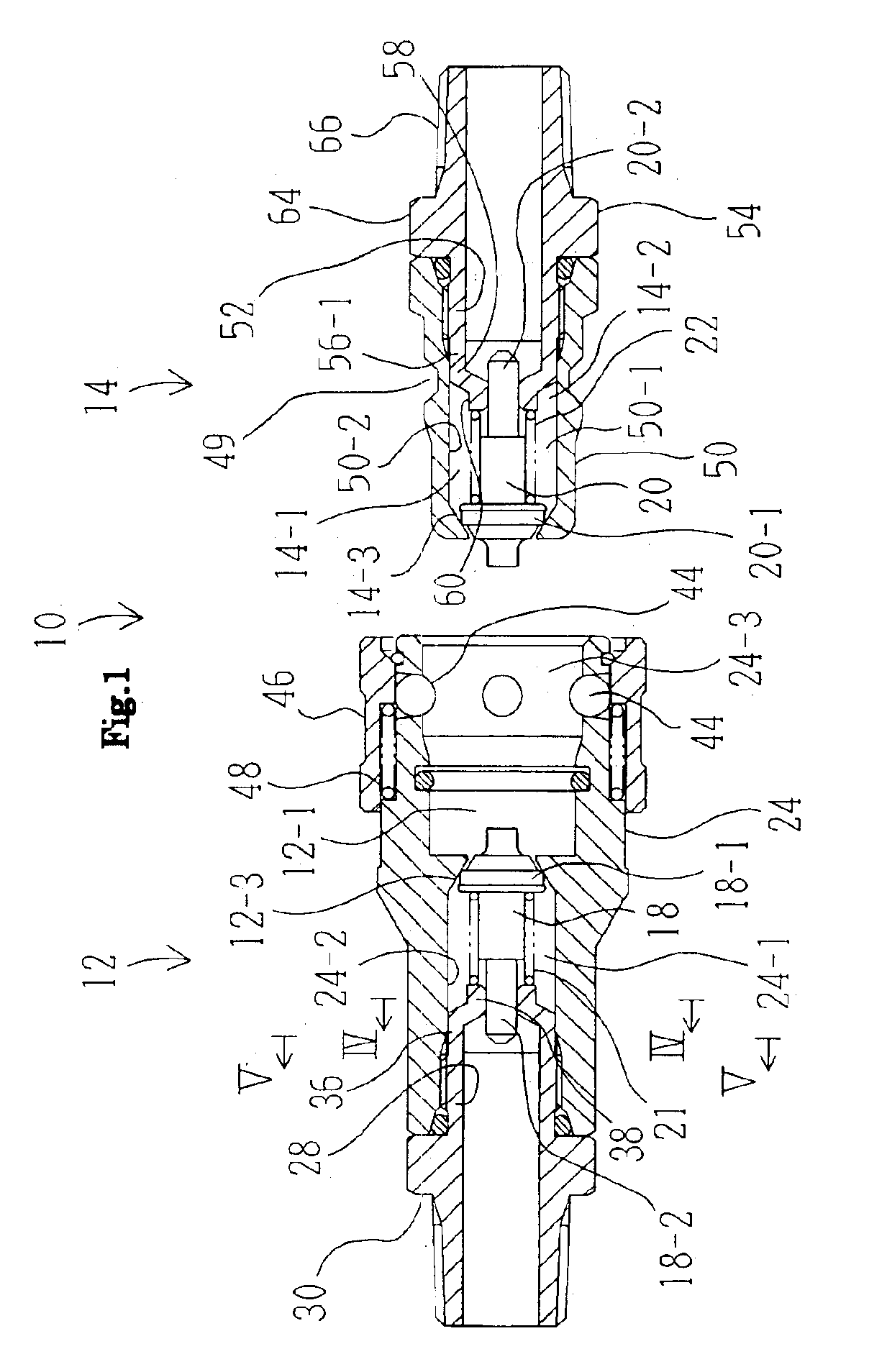
[0028]FIG. 1 shows a female coupler 12 and a male coupler 14 of a pipe coupling 10 according to the present invention.

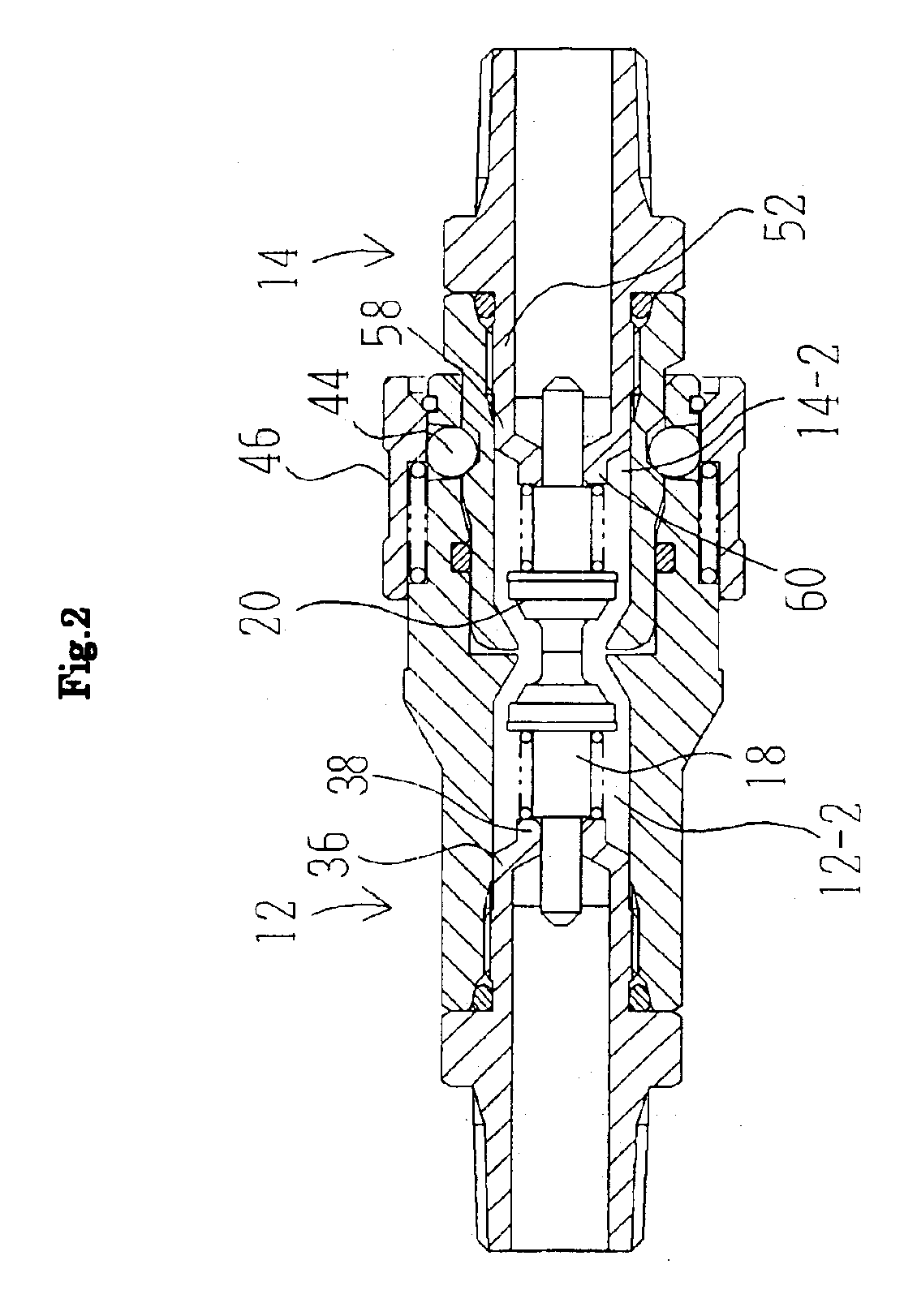
[0029]The female coupler 12 and the male coupler 14 have valve elements 18 and 20 provided in respective fluid passages 12-1 and 14-1. The valve elements 18 and 20 are urged by compression springs 21 and 22, respectively. When the female coupler 12 and the male coupler 14 are separate from one another, as shown in FIG. 1, the valve elements 18 and 20 are in engagement with annular valve seats 12-3 and 14-3 formed in the fluid passages 12-1 and 14-1 of the female coupler 12 and the male coupler 14, thereby closing the respective fluid passages 12-1 and 14-1. When the male coupler 14 is inserted into the female coupler 12 and is thus connected thereto, the distal ends of the valve elements 18 and 20 ...


PUM


Abstract

A female coupler and a male coupler of a pipe coupling that are easy to assemble and have a minimized passage resistance are provided. The female coupler includes a cylindrical female coupler body adapted to receive the male coupler from a front end opening thereof. A pipe connection adapter has a cylindrical connecting portion that is inserted into the female coupler body from a rear end opening thereof, and is thus connected to the female coupler body. The pipe connection adapter has two support legs extending from the front end surface of the cylindrical connecting portion. A valve support ring is secured to the distal ends of the support legs. The valve support ring has an outer circumferential surface that has a diameter smaller than the outer diameter of the cylindrical connecting portion, whereby a fluid passage is defined between the outer circumferential surface of the support ring and the wall surface of the through-hole of the female coupler body. The support legs are connected to the valve support ring at the rear end surface thereof. The male coupler has an arrangement similar to the above.

Description

[0001]This application claims priority under 35 U.S.C. §119 to Japanese Patent Application No. 2003-155367 filed May 30, 2003, the entire content of which is hereby incorporated by reference.BACKGROUND OF THE INVENTION[0002]1. Field of the Invention[0003]The present invention relates to a pipe coupling including a female coupler and a male coupler that are connected to one another.[0004]2. Description of the Related Art[0005]A female coupler and a male coupler, which together constitute a pipe coupling, may be provided in their respective fluid passages with a valve to enable opening or closing of the passages. These valves are supported in the respective passages by using valve support members. The valve support members are prepared separately from the female coupler body and the male coupler body and, during assembly, they are fitted into the female coupler body and the male coupler body, respectively (for example, see Japanese Utility Model Application Post-Examination Publicatio...

Claims


Application Information

Patent Timeline
Patent Type & Authority Patents(United States)
IPC IPC(8): F16L37/28F16L37/32F16L37/23
CPCF16L37/32Y10T137/87949Y10T137/87957
Inventor MIKIYA, TOSHIOYAMASHITA, JIN
Owner NITTO KOHKI CO LTD
Why Eureka
Try Eureka