Fluid machinery

a technology of machinery and fluids, applied in the direction of machines/engines, liquid fuel engines, rotary/oscillating piston pump components, etc., can solve the problems of inconvenient and disadvantageous, limit the type of machinery,

Inactive Publication Date: 2005-05-03
TOSHIBA CARRIER CORP
View PDF9 Cites 26 Cited by
  • Summary
  • Abstract
  • Description
  • Claims
  • Application Information

AI Technical Summary

Benefits of technology

[0013]An object of the present invention is therefore to substantially eliminate defects or drawbacks encountered in the prior art mentioned above and to pr

Problems solved by technology

The conventional helical compressor 71 is provided with one helical groove 74 and one helical blade 72, and accordingly, only a single dr

Method used


Image

  • Fluid machinery
  • Fluid machinery
  • Fluid machinery

Examples


Embodiment Construction

[0034]A preferred embodiment of the present invention will be described hereunder with reference to the accompanying drawings.

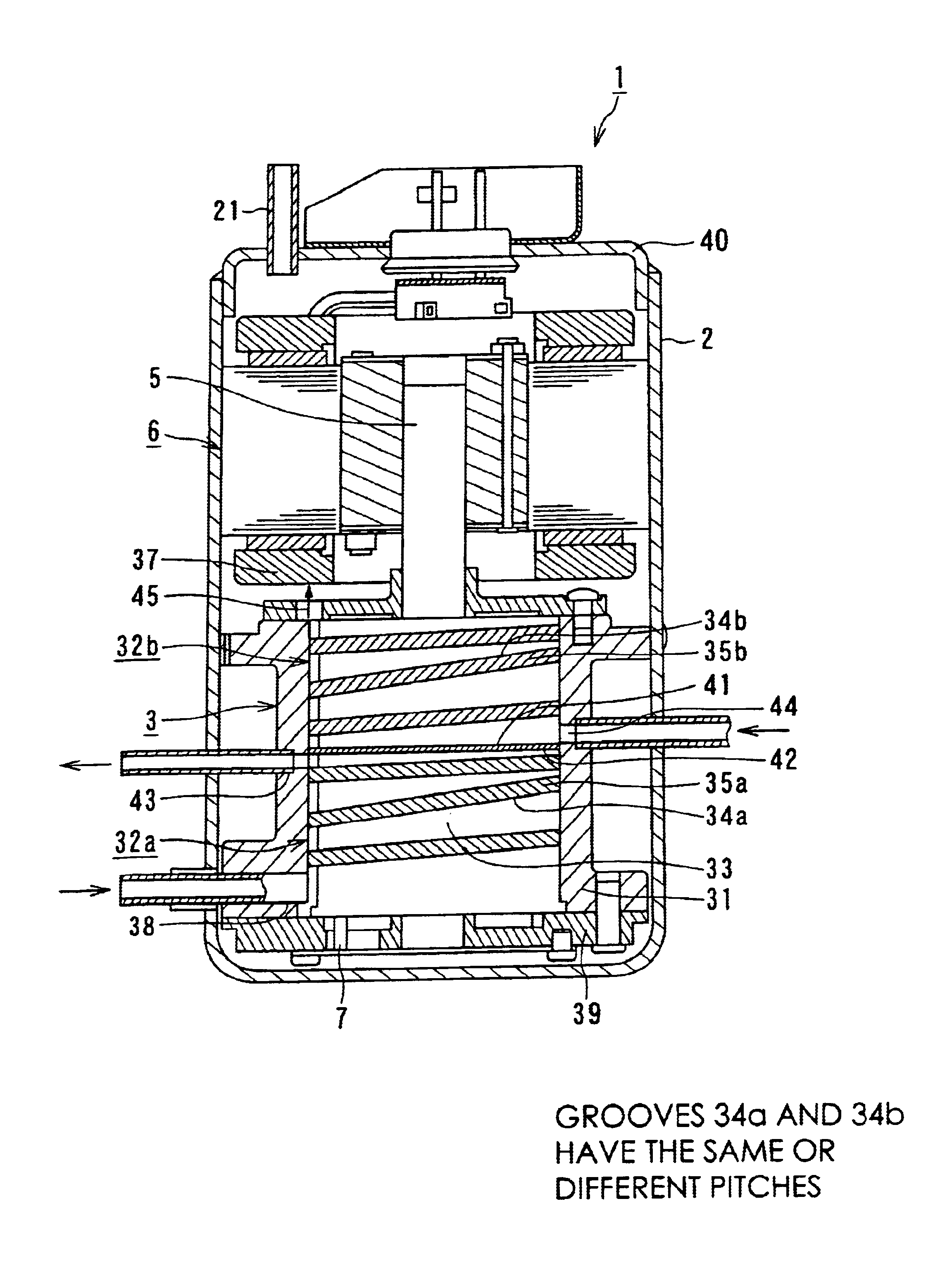
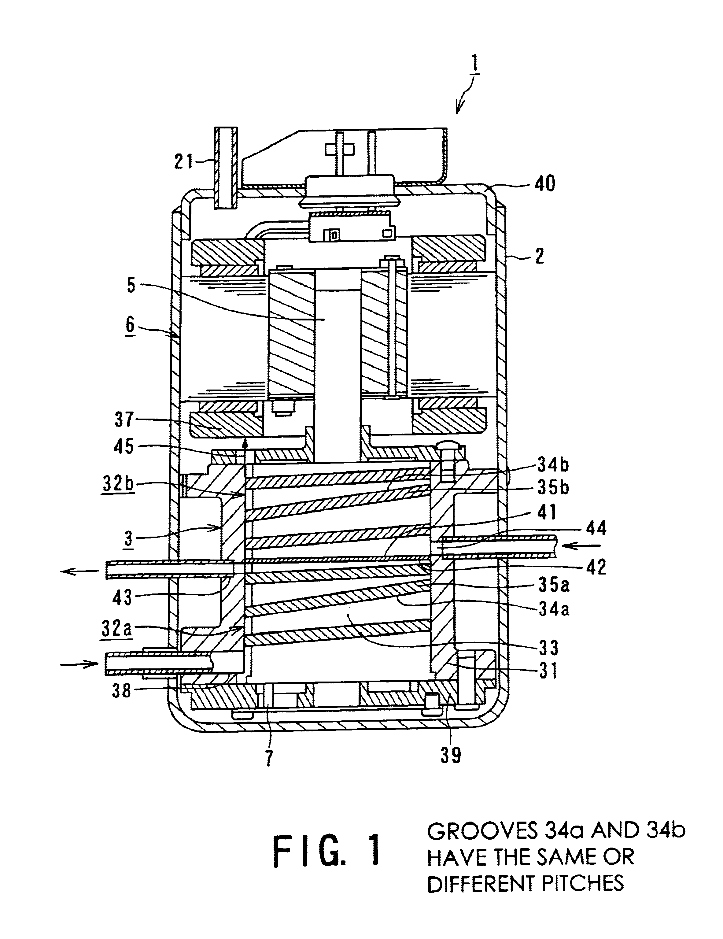
[0035]First, with reference to FIG. 1, showing a first embodiment of a fluid machinery or machine according to the present invention, the fluid machinery of this embodiment is a vertical-type helical compressor 1. This helical compressor 1 comprises an outer seal casing 2, a helical mechanism 3 disposed inside the casing 2 and a driving mechanism 6, which is also disposed inside the casing 2, as electric motor which drives the helical mechanism 3 through a crank shaft 5.

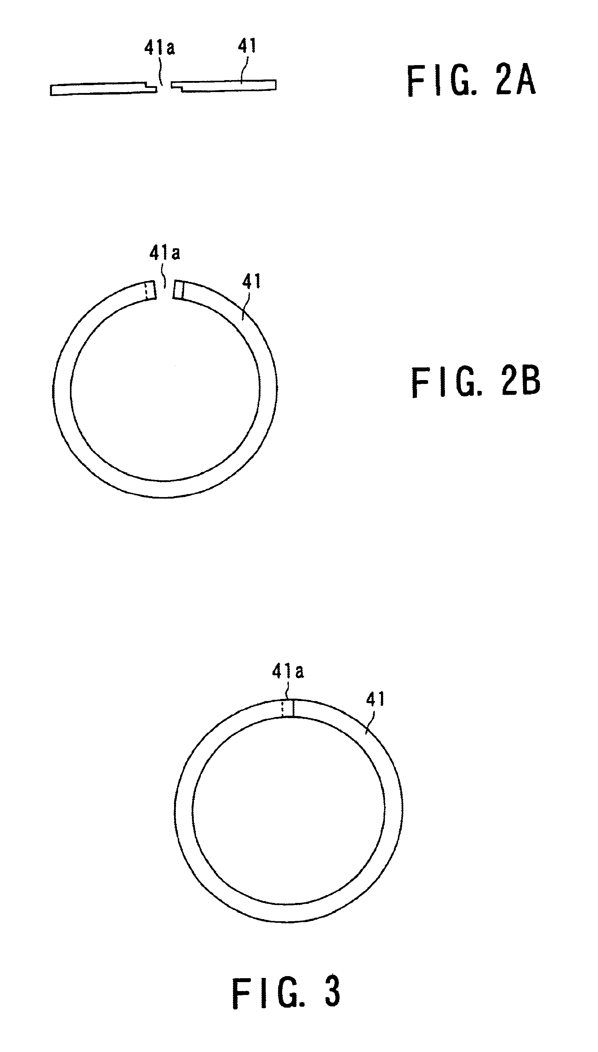
[0036]The helical mechanism 3 is provided with a single cylinder, i.e., cylinder block 31 and sectioned into a plurality of helical mechanisms provided with operation sections such as two in the illustrated embodiment, i.e., a lower operation section 32a and an upper operation section 32b. These lower and upper operation sections 32a and 32b are sectioned, as independent operation chambers, by...


PUM


Abstract

A fluid machinery includes a helical mechanism connected to a driving mechanism, which is driven via a crank shaft. The helical mechanism includes a cylinder defining an inner space, a roller disposed inside the cylinder so as to be rotated in an eccentric manner, the roller being formed with a plurality of helical grooves on an outer peripheral surface, and at least one seal ring groove between respective helical grooves, a plurality of helical blades fitted to the helical grooves so as to be disposed between as inner peripheral surface of the cylinder and the outer peripheral surface of the roller, and at least one seal ring fitted to the seal ring groove so as to tightly seal the inner space as a plurality of operation sections. Furthermore, a plurality of suction ports and a plurality of drain ports, associated with respective operation sections, communicate with each other.

Description

BACKGROUND OF THE INVENTION[0001]1. Field of the Invention[0002]The present invention relates to a fluid machinery or machine having a helical mechanism provided with a plurality of operation sections or chambers in a single cylinder.[0003]2. Related Art[0004]In a know art, there is provided a helical compressor having a helical mechanism such as shown in FIG. 6.[0005]With reference to FIG. 6, a reference numeral 70 denotes a helical compressor, which generally comprises a helical mechanism 71 and a driving mechanism 77 such as electric motor. The helical mechanism 71 includes a cylinder or cylinder block 75 in which a roller 73 is disposed. The roller 73 is rotated, through a crank shaft 79, driven by the driving mechanism 77 in an eccentric manner.[0006]The roller 73 is formed, on its outer peripheral surface, with a helical groove 74 into which a helical blade 72 is fitted so as to be disposed in a space between the outer peripheral surface of the roller 73 and an inner periphera...

Claims


Application Information

Patent Timeline
IPC IPC(8): F04C18/08F04C18/107F04C23/00F04C2/344F04C18/344
CPCF04C23/001F04C18/107
Inventor FUJIWARA, TAKAYOSHI
Owner TOSHIBA CARRIER CORP
Why Eureka
Try Eureka