Cable end connector assembly and the method of making the same

Inactive Publication Date: 2005-05-03
HON HAI PRECISION IND CO LTD
View PDF12 Cites 27 Cited by
  • Summary
  • Abstract
  • Description
  • Claims
  • Application Information

AI Technical Summary

Benefits of technology

[0007]An object of the present invention is to provide a cable en

Problems solved by technology

However, firstly it requires initially making a contact module via insert molding which complicates the manufacturing process and costs more money in comparison with the traditiona

Method used


Image

  • Cable end connector assembly and the method of making the same
  • Cable end connector assembly and the method of making the same
  • Cable end connector assembly and the method of making the same

Examples


Embodiment Construction

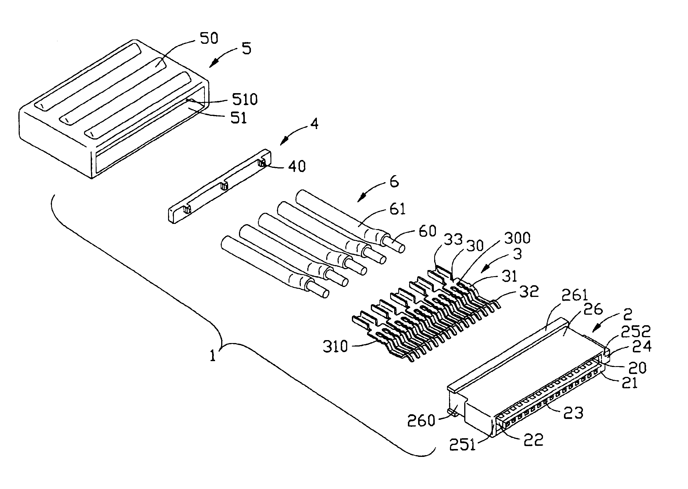
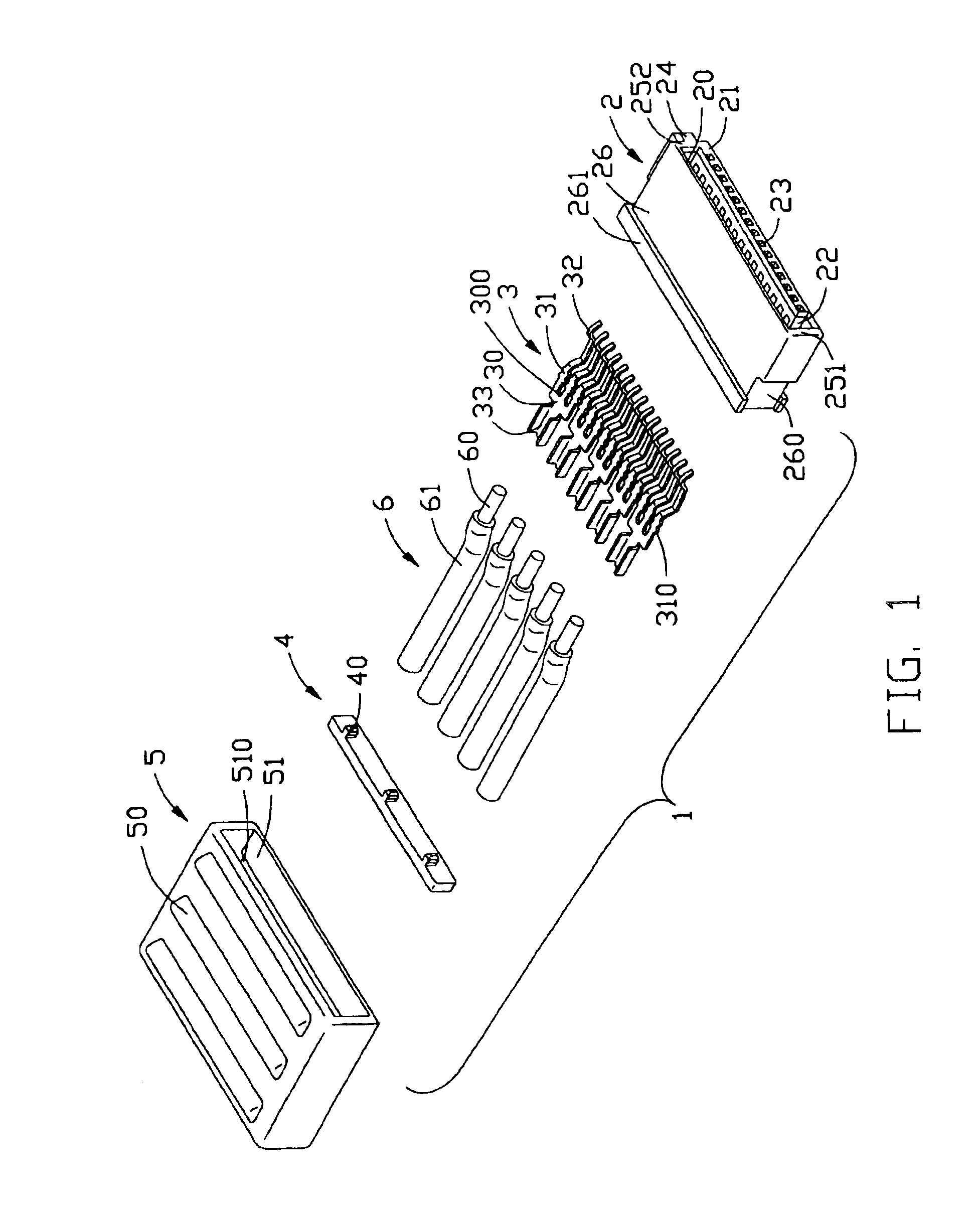
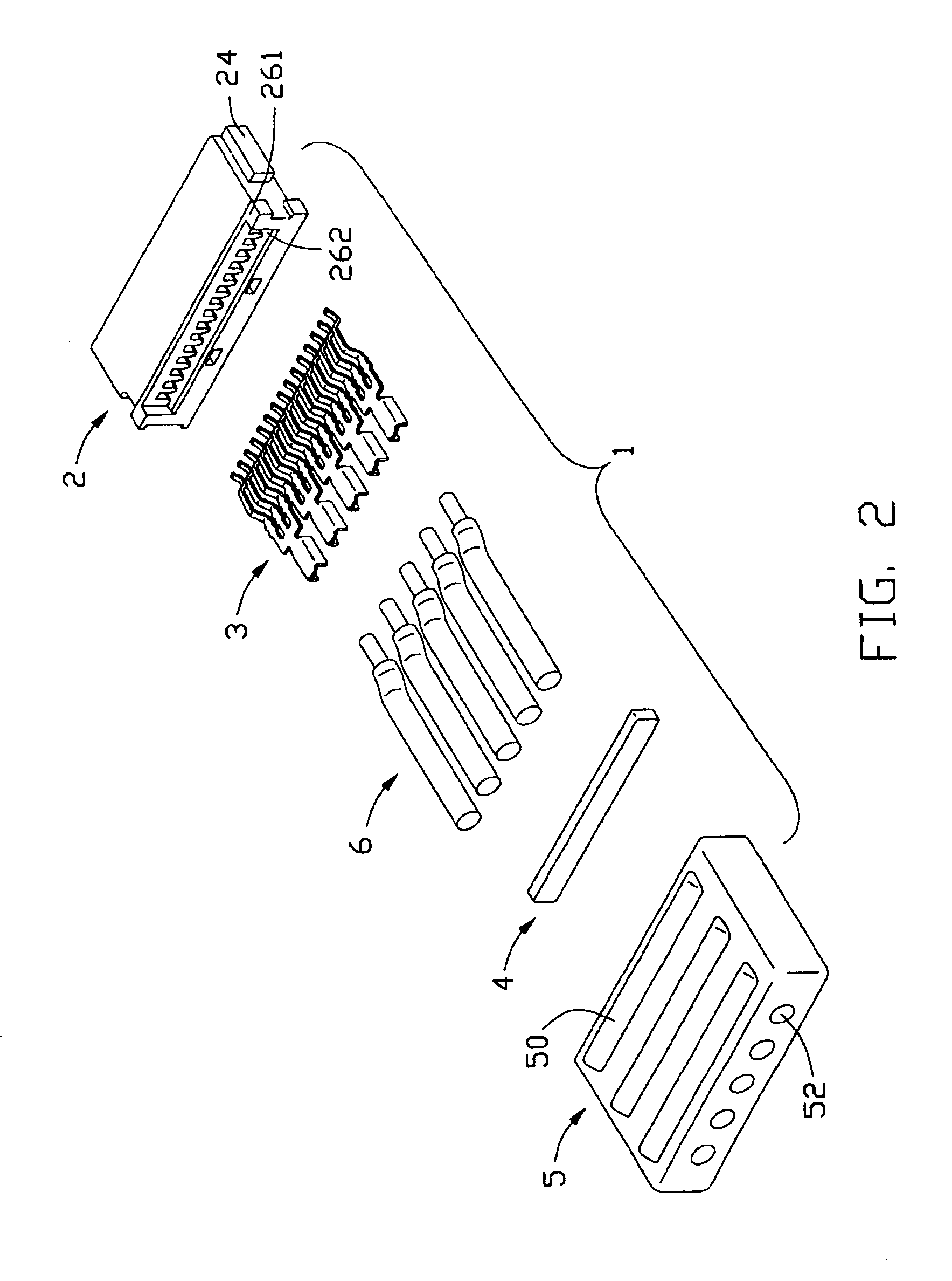
[0019]Referring to FIGS. 1 and 2, and in conjunction with FIG. 3, a cable end connector assembly 1 in accordance with the present invention comprises a dielectric housing 2, a plurality of contact units 3, a spacer 4, a cover 5, and a plurality of wires 6. In the preferred embodiment of the present invention, the cable end connector assembly 1 is in the form of a Serial ATA cable end connector assembly.

[0020]The dielectric housing 2 comprises an upper wall 20, a lower wall 21 opposite to the upper wall 20, and first and second sidewalls 251, 252 connecting the upper and lower walls 20, 21. The upper wall 20, the lower wall 21, and the first and second sidewalls 251, 252 together define an L-shaped receiving space 22 in a front end of the housing 2. A slit 220 is defined between the upper and lower walls 20, 21 from a rear end 26 of the housing 2 and communicates with the receiving space 22. A plurality of dividing blocks 210 is formed on the lower wall 21 of the housing 2. A passage...


PUM


Abstract

A cable end connector assembly (1) includes a dielectric housing (2), a plurality of contact units (3), a plurality of wires (6), and a cover (5). The housing includes an upper wall (20), a lower wall (21), and a pair of sidewalls (251, 252) connecting the upper and lower walls. Each contact unit comprises at least one mating portion (32) and a tail portion (33) opposite to the mating portion and extending beyond a rear face of the housing. The tail portion has a U-shaped configuration. Each wire comprises a conductive core (60) received in corresponding U-shaped tail portion and soldered with the tail portion to form electrical connection therebetween. The cover is over-molded with a rear end (26) of the housing and covers front ends of the wires and the tail portions of the contact units to protect the electrical connection between the wires and the contact units.

Description

BACKGROUND OF THE INVENTION[0001]1. Field of the Invention[0002]The present invention generally relates to a cable end connector assembly, and more particularly to a Serial Advanced Technology Attachment (Serial ATA) cable end connector assembly which can reliably and securely terminate wires of a cable for providing good transmission performances.[0003]2. Description of Related Art[0004]A cable end connector assembly needs to terminate wires of a cable. Connection of wires of a cable with terminals of a connector can be attained in several ways, such as by applying the insulation displacement connection (IDC) technology, by using a printed circuit board which interconnects the cable and the connector, or by applying the crimp technology.[0005]There also exists in the art an electrical connector known as a Serial ATA connector which is generally used for disk drives and storage peripherals connecting with a mother board. A Serial ATA cable end connector assembly comprises a housing ...

Claims


Application Information

Patent Timeline
IPC IPC(8): H01R13/58H01R43/02H01R4/02
CPCH01R43/0249H01R13/5845H01R4/023H01R43/0263
Inventor LEE, GEORGE
Owner HON HAI PRECISION IND CO LTD
Why Eureka
Try Eureka