
Method for manufacturing piezoelectric interlinings

A manufacturing method and interlayer technology, which are used in material analysis, measuring devices, and instruments using sonic/ultrasonic/infrasonic waves, which can solve the problem of low connection strength, "island" electrodes that are easy to fall off, and difficult to play a protective role, etc. question

Inactive Publication Date: 2013-12-25
SUZHOU PUWEIDI IND AUTOMATION CO LTD
View PDF2 Cites 0 Cited by
  • Summary
  • Abstract
  • Description
  • Claims
  • Application Information

AI Technical Summary

Problems solved by technology

However, since the piezoelectric sheet electrode is only a thin conductive layer covering the piezoelectric sheet, such as conductive silver paste, the "island" in the two electrodes is very small, and the connection strength between the piezoelectric sheet and the piezoelectric sheet is not high. ; while the flexible circuit in the piezoelectric interlayer is relatively soft, and is connected to the electrode of the piezoelectric sheet by welding or conductive glue. It is easy to be pulled between the piezoelectric sheet during manufacturing, carrying and installation, and it is difficult to play a protective role. This will cause the "island" electrodes to fall off very easily, making the piezoelectric interlayer ineffective.
The method of adding a protective film to the piezoelectric sheet position of the piezoelectric interlayer will affect the coupling effect between the piezoelectric sheet and the structure and reduce the performance of the piezoelectric interlayer.

Method used


Image

  • Method for manufacturing piezoelectric interlinings
  • Method for manufacturing piezoelectric interlinings
  • Method for manufacturing piezoelectric interlinings

Examples


Embodiment Construction

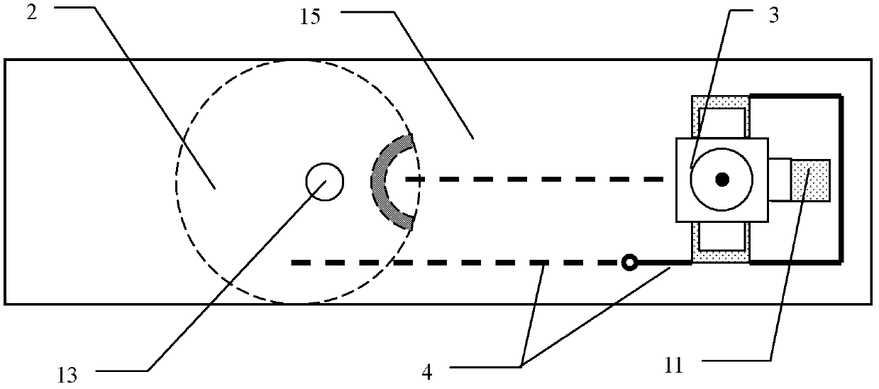
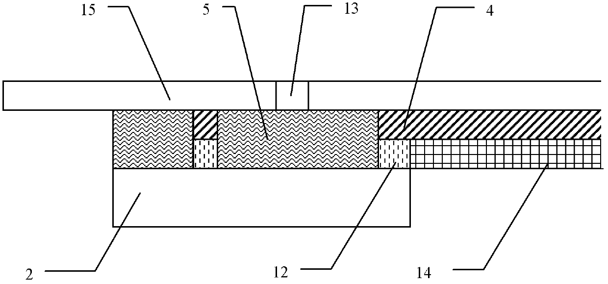
[0020] The implementation process of the present invention will be described in detail below in conjunction with the accompanying drawings.

[0021] The invention provides a method for manufacturing a piezoelectric interlayer, which is used to make a piezoelectric interlayer by using a flexible circuit board, a piezoelectric sheet and a general interface, and the piezoelectric sheet is used as an actuator / sensor element, specifically comprising the following steps:

[0022] (1) Reserve the position of the circuit pad on one side of the flexible circuit board according to the electrode position of the piezoelectric sheet, and reserve the position of the pin pad of the general interface on the other side of the flexible circuit board, and then place the flexible circuit board The remaining areas of the board are all covered with an insulating layer to prevent short circuits during use;

[0023] (2) Establish a circuit connection between the pin pad on the flexible circuit board ...


PUM


Abstract

The invention discloses a method for manufacturing piezoelectric interlinings. According to the method, a piezoelectric interlining is prepared by using a flexible circuit board, a piezoelectric patch and a universal interface. The method comprises the following steps: reserving a circuit pad on one side of the flexible circuit board according to the position of the electrode of the piezoelectric patch, and reserving a pin pad of the universal interface on the other side of the flexible circuit board, and covering the remaining positions of the flexible circuit board completely by using an insulating layer; conducting the pin pad on the flexible circuit board with the universal interface by way of welding or conductive adhesive connection, and then conducting the circuit pad on the flexible circuit board with the electrode of the piezoelectric patch by way of welding or conductive adhesive connection, thereby implementing the circuit connection between the electrode of the piezoelectric patch and the universal interface; and carrying out mutual connection and reinforcement on areas (except for the electrode) of the junction surfaces of the flexible circuit board and the piezoelectric patch by using an adhesive layer. By using the method disclosed by the invention, the connection strength between the flexible circuit board and the piezoelectric patch can be enhanced so as to protect the electrical connection of the electrode and improve the reliability of the piezoelectric interlining.

Description

technical field [0001] The invention belongs to the technical field of structural damage monitoring, and relates to a method for designing and manufacturing piezoelectric interlayers, in particular to a method for reinforcing piezoelectric elements during the manufacturing process. Background technique [0002] With the continuous improvement of structural safety and reliability requirements, the on-line monitoring and diagnosis of structural damage has attracted people's attention. [0003] Since it is sensitive to small damages such as cracks and delaminations, structural damage monitoring and diagnosis technology based on piezoelectric elements and Lamb wave methods is one of the most effective technical methods at present. This technical method integrates a certain number of piezoelectric actuators and sensors on the surface or inside of the structure (using the positive and negative piezoelectric effects of piezoelectric elements), excites the Lamb wave signal in the st...

Claims


Application Information

Patent Timeline
Patent Type & Authority Patents(China)
IPC IPC(8): G01N29/22
Inventor 王强江兵袁慎芳
Owner SUZHOU PUWEIDI IND AUTOMATION CO LTD
Learn More