Electrolytic tank integrated structure based on alkaline water electrolysis hydrogen production process

An electrolyzer and electrolyzed water technology, applied in the field of electrolyzers, can solve the problems of cumbersome and time-consuming disassembly and replacement of electrodes and electrolyzers, and affect the efficiency of hydrogen production, so as to achieve convenient disassembly, prolong service life, and improve frictional fastening degree of effect

Active Publication Date: 2022-01-21
SICHUAN HUANENG HYDROGEN TECH CO LTD +9
View PDF5 Cites 0 Cited by
  • Summary
  • Abstract
  • Description
  • Claims
  • Application Information

AI Technical Summary

Problems solved by technology

[0004] At present, the electrodes of hydrogen production by electrolysis of water will wear out during long-term use, and the disassembly and replacement operations between the electrodes and the electrolytic cell are

Method used


Image

  • Electrolytic tank integrated structure based on alkaline water electrolysis hydrogen production process
  • Electrolytic tank integrated structure based on alkaline water electrolysis hydrogen production process
  • Electrolytic tank integrated structure based on alkaline water electrolysis hydrogen production process

Examples


Embodiment 1

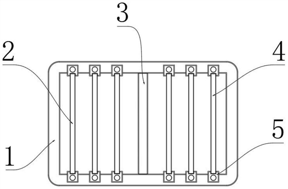
[0027] Please refer to figure 1 , image 3 and Figure 5 As shown, the present invention provides an electrolytic cell integrated structure based on alkaline electrolyzed water hydrogen production process, comprising an electrolytic cell body 1, a first pole plate 2, a second pole plate 4 and a diaphragm 3, the first pole plate The sheet 2 is arranged on one side of the electrolytic cell body 1, the electrolytic cell body 1 is arranged on the other side of the electrolytic cell body 1, and the diaphragm 3 is isolated on the first plate sheet inside the electrolytic cell body 1 2 and the second pole plate 4, the first pole plate 2 and the second pole plate 4 are the positive pole and the negative pole respectively, or the first pole plate 2 and the second pole plate 4 are the negative pole and the positive pole respectively, The inner side wall of the electrolytic cell body 1 is connected and fixed with a square column 5, and a guide chute 11 is provided axially from the squa...

Embodiment 2

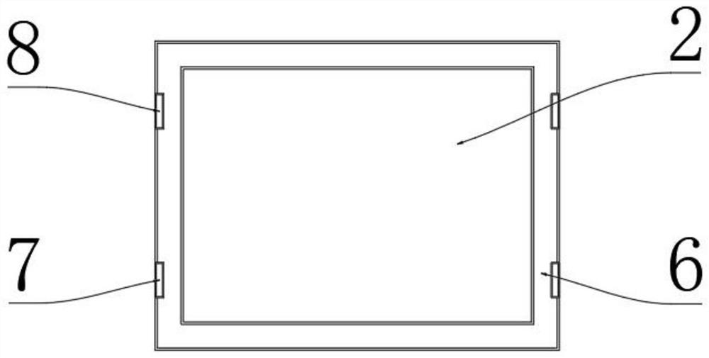
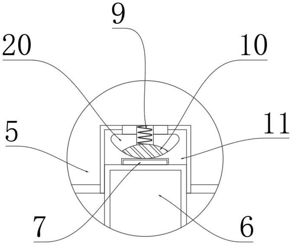
[0030] Such as figure 1 , figure 2 and image 3 As shown, the present invention discloses that the inner side wall of the electrolytic cell body 1 is connected and fixed with a square column 5, and a guide chute 11 is provided axially from the square column 5 to the top, and the side wall of the guide chute 11 is connected with an electrode conductive contact. Point 10, the side walls of the first pole plate 2 or the second pole plate 4 are slidingly engaged with the guide chute 11, and the side walls of the first pole plate 2 and the second pole plate 4 are covered An outer frame 6 is provided, and the side wall of the outer frame 6 is connected with a conductive piece 7, and the inner end of the conductive piece 7 is electrically connected with the first plate piece 2 or the second plate piece 4, and the end of the conductive piece 7 is electrically connected. The outer end and the electrode conductive contact 10 are in contact with each other. The electrode conductive co...

Embodiment 3

[0032] Such as figure 1 , figure 2 and Figure 4As shown, the present invention discloses that the inner side wall of the electrolytic cell body 1 is connected and fixed with a square column 5, and a guide chute 11 is provided axially from the square column 5 to the top, and the first plate piece 2 or the second plate piece 4 The side walls of the outer frame 6 are all slided and engaged with the guide chute 11, the inner wall of the guide chute 11 is provided with a movable groove 14, and the side wall of the outer frame 6 is provided with a positioning groove 16 relative to the movable groove 14, and the movable groove 14 and the positioning groove A steel ball 15 is clamped between 16, and the outer port of the movable groove 14 is covered with a limit ring 13. The diameter of the inner hole of the limit ring 13 is between the radius and diameter of the steel ball 15, and the steel ball 15 is movably arranged on the movable Inside the groove 14, the inner inner wall of t...


PUM


Abstract

The invention discloses an electrolytic tank integrated structure based on an alkaline water electrolysis hydrogen production process. The electrolytic bath integrated structure comprises an electrolytic bath body, a first pole plate piece, a second pole plate piece and a diaphragm, a square column is fixedly connected to the inner side wall of the electrolytic bath body, and a guide sliding groove is axially formed from the square column to the top. The side wall of the first polar plate piece or the side wall of the second polar plate piece is in sliding clamping connection with the guide sliding groove, a wiring groove is formed in the top of the square column, the side wall of the guide sliding groove is connected with an electrode conductive contact, the electrode conductive contact is electrically connected with the wiring groove, and the first polar plate piece or the second polar plate piece is electrically connected with the electrode conductive contact. The first polar plate piece or the second polar plate piece is clamped and fixedly connected with the square column through the guide sliding groove, an external cable is fixed through the wiring groove and electrically connected with the electrode conductive contact, the first polar plate piece or the second polar plate piece abuts against and is attached to the electrode conductive contact in the guide sliding groove, and the first polar plate piece or the second polar plate piece normally supplies power to operate. The first polar plate piece or the second polar plate piece is convenient to disassemble and assemble.

Description

technical field [0001] The invention relates to the technical field of electrolyzers, in particular to an integrated structure of electrolyzers based on the hydrogen production process of alkaline electrolyzed water. Background technique [0002] At present, a new round of energy technology revolution is emerging around the world, and the international energy pattern is also undergoing profound changes. Renewable energy is gradually becoming the main source of new electricity, and the structure and operation mode of the power grid will undergo major changes. The energy utilization medium of carbon can realize the large-scale consumption of fluctuating renewable energy. Hydrogen has the dual attributes of energy and material connection, and is an important link for the extension of electric energy to replace fossil fuels in various industries. It does not emit air during use Therefore, the development of the hydrogen energy industry is an important way to deal with the above ...

Claims


Application Information

Patent Timeline
IPC IPC(8): C25B9/63C25B9/65
CPCC25B9/63C25B9/65Y02E60/36Y02P20/133
Inventor 李太斌张冲程莹涂维党庞飞敬一枫袁志镭马星粟丽蓉郭荣鑫周心怡何鹏
Owner SICHUAN HUANENG HYDROGEN TECH CO LTD
Why Eureka
Try Eureka