Pressure/force computer controlled drug delivery system with automated charging

Inactive Publication Date: 2005-05-03
MILESTONE SCIENTIFIC INC
View PDF18 Cites 74 Cited by
  • Summary
  • Abstract
  • Description
  • Claims
  • Application Information

AI Technical Summary

Benefits of technology

[0012]The present invention has for its objective to minimize subjective pain response and any potential tissue damage t

Problems solved by technology

Line blockage would cause pressure in the syringe to increase.
However, these systems do not provide a means for drug delivery subcutaneously via a hypodermic needle.
Moreover these systems do not provide a means of aspiration during drug delivery, which is a medical requirement for subcutaneous injection in an attempt to avoid intravascular placement of the hyp

Method used


Image

  • Pressure/force computer controlled drug delivery system with automated charging
  • Pressure/force computer controlled drug delivery system with automated charging
  • Pressure/force computer controlled drug delivery system with automated charging

Examples


Embodiment Construction

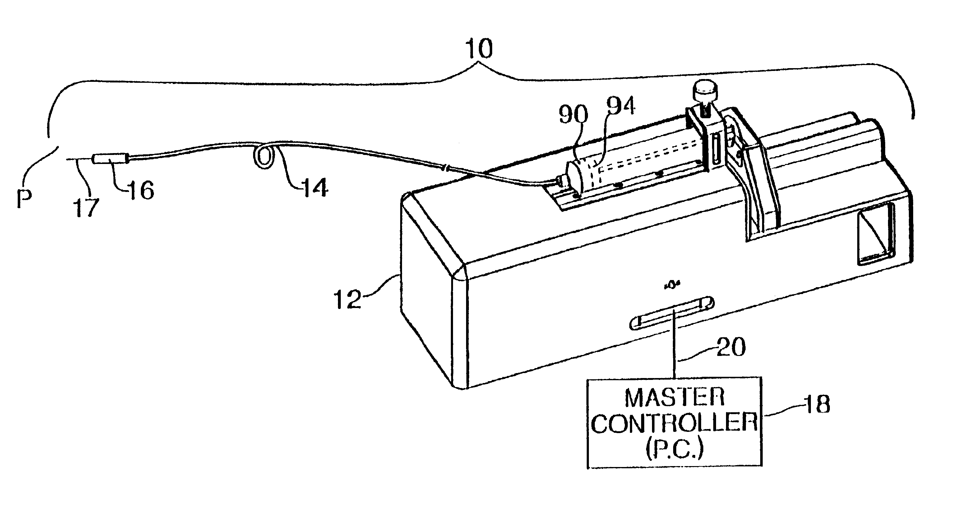
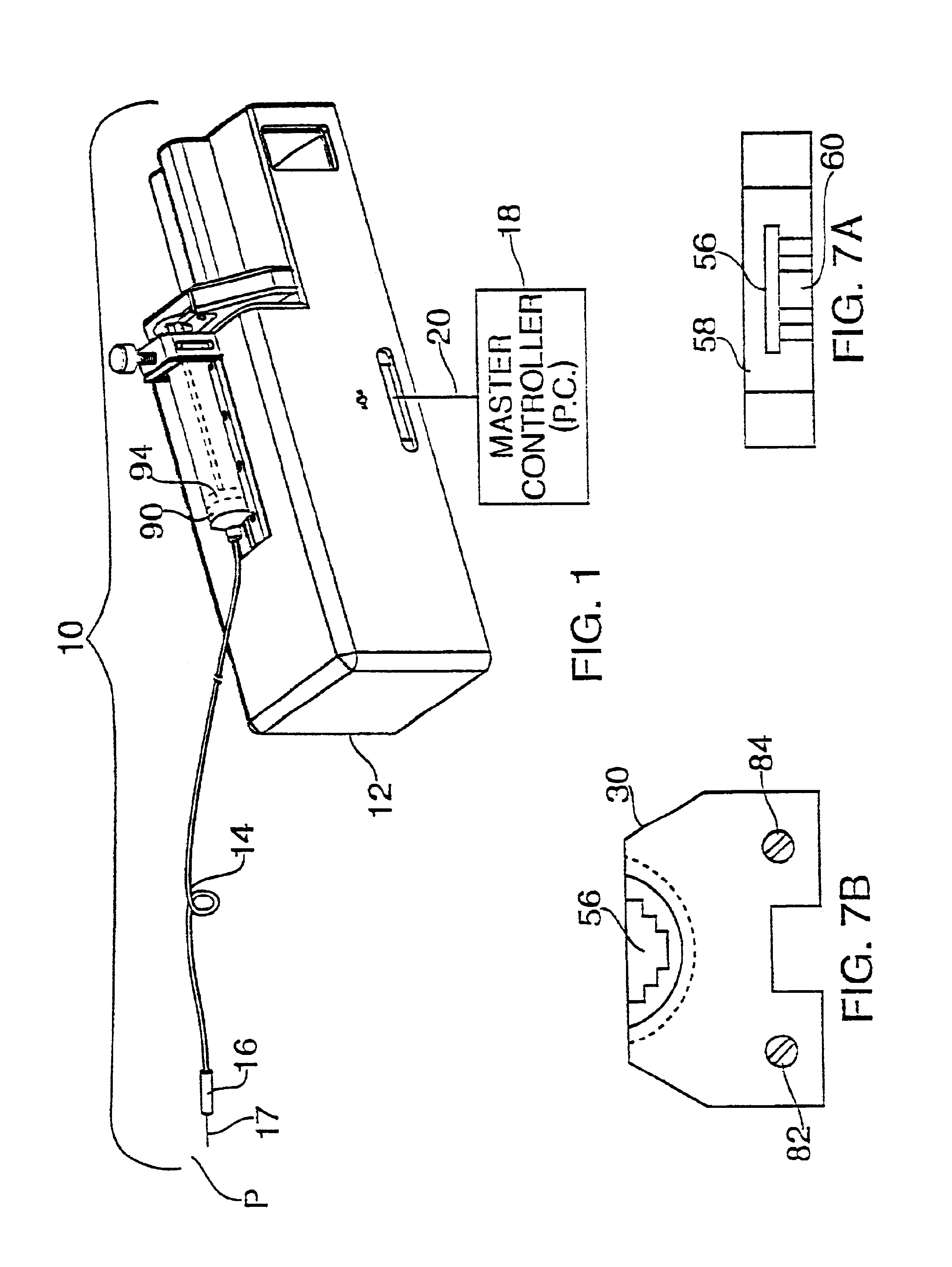
[0048]The subject invention pertains to a system for delivering drugs such as an anesthetic, or to provide aspiration, for example for a biopsy, in an efficient manner which insures at the same time that pain to the patient is minimized. The system includes a mechanical assembly cooperating with an electronic controller.

[0049]The mechanical assembly is illustrated in FIGS. 1-9 and the electronic controller 150 is shown in FIGS. 10-18.

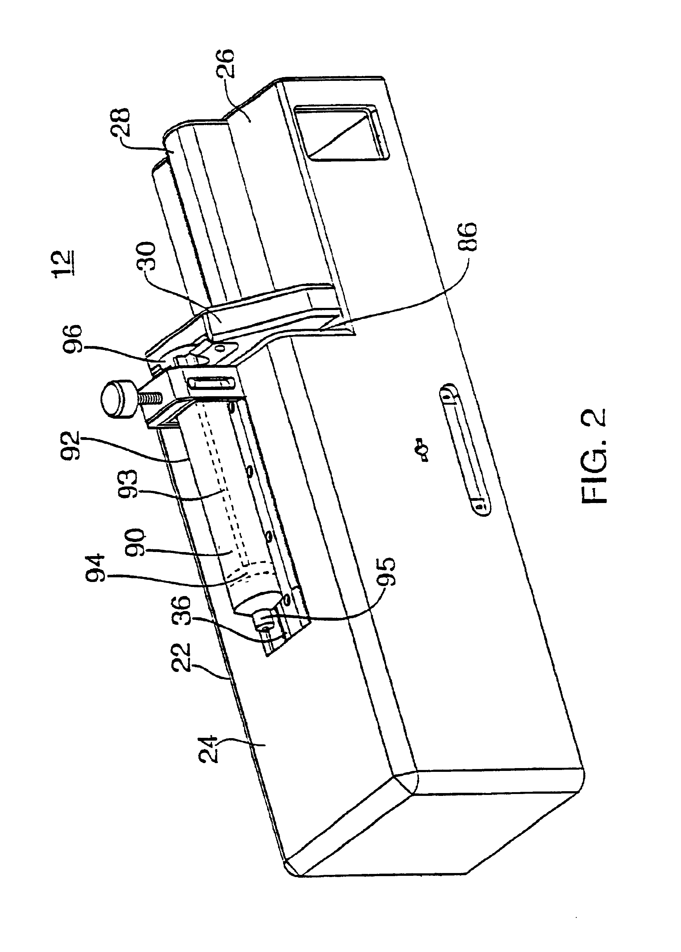
[0050]A drug delivery system 10 constructed in accordance with this invention includes drive mechanism 12, a delivery tube 14 and a handle 16 terminating with a needle 17. More particularly, a syringe 90 (or other fluid storage device) is mounted on the drive mechanism with one end of tube 14 being coupled to the syringe 90. The drive mechanism 12 operates a plunger 94 to selectively eject fluid out through the tube 14 handle 16, and needle 17 or alternatively to draw fluid in. The drive mechanism 12 is associated with an external controller for selecti...


PUM


Abstract

An automatic injection device includes a drive mechanism and a sensor used to determine an internal characteristic such as a force or internal pressure generated during an injection process. This characteristic is then used as a control parameter by a microprocessor or controller which generates corresponding commands to the drive mechanism. In a particularly advantageous embodiment, the characteristic is used to calculate an exit pressure at which fluid ejected by the device through an elongated tube. The drive mechanism is then operated in such a manner that the exit pressure is maintained at a predetermined level to insure that a patient does not suffer pain and/or tissue damage.

Description

RELATED APPLICATIONS[0001]This application claims priority to U.S. Provisional Application Ser. No. 60 / 081,388 filed Apr. 10, 1998, incorporated herein by reference, and is a continuation of U.S. patent application Ser. No. 09 / 201,464 filed Nov. 30, 1998, now U.S. Pat. No. 6,200,289.BACKGROUND OF THE INVENTION[0002]a. Field of Invention[0003]The present invention relates generally to improvements to the delivery of drugs, particularly to systems for subcutaneous injection / aspiration (syringes) for drug delivery providing intermittent, episodic or limited drug delivery (as opposed to continuous drug delivery of syringe pumps). More specifically, this invention relates to an improved means of subcutaneous drug (fluid) injection and aspiration, providing a means and method of controlling and monitoring the interaction of specific flow rate and pressure during fluid injection and aspiration with a hypodermic hollow-core needle.[0004]b. Description of the Prior Art[0005]Infusion pumps de...

Claims


Application Information

Patent Timeline
IPC IPC(8): A61M5/168A61M5/145A61M1/00A61M5/00A61M31/00A61M37/00
CPCA61M5/1456A61M5/16854Y10S128/12A61M1/00
Inventor HOCHMAN, MARKHOCHMAN, CLAUDIAASCIONE, ANGELOBROWN, LAWRENCEJOHNSON, HARDIELOCKWOOD, MICHELLE
Owner MILESTONE SCIENTIFIC INC
Why Eureka
Try Eureka