Insertion catheter for vascular prosthesis

a technology for vascular prosthesis and insertion catheter, which is applied in the field of insertion catheter, can solve the problems of inability to define the guidance of the vascular prosthesis during insertion, and achieve the effects of easy access, easy removal, and increased friction between the grip part and the catheter cover

Inactive Publication Date: 2005-05-03
AESCULAP AG
View PDF14 Cites 54 Cited by
  • Summary
  • Abstract
  • Description
  • Claims
  • Application Information

AI Technical Summary

Benefits of technology

[0046]Furthermore, provision may advantageously be made for the holding body to be radially at least partially surrounded by the guide body in an inserting position of the insertion catheter. The holding body is thereby protected by the guide body during insertion of the catheter.
[0047]To insert the vascular prosthesis, the proximal end of the catheter can be gripped by an operator. For this purpose, provision is advantageously made for a grip part surrounding the catheter cover to be provided at the proximal end thereof. In this way, the operator can hold and guide the catheter safely.
[0048]For optimum guidance of the catheter by the operator it is advantageous for him to always be able to grip the catheter in the proximity of a point at which the catheter is introduced into the patient's body, in particular, for the catheter cover to be bendable. For this purpose, it is advantageous for the grip part to be displaceable relative to the catheter cover.
[0049]In a preferred embodiment o

Problems solved by technology

A defined guidance of the vascular prosthesis during insertion is therefore not possible w

Method used


Image

  • Insertion catheter for vascular prosthesis
  • Insertion catheter for vascular prosthesis
  • Insertion catheter for vascular prosthesis

Examples


Embodiment Construction

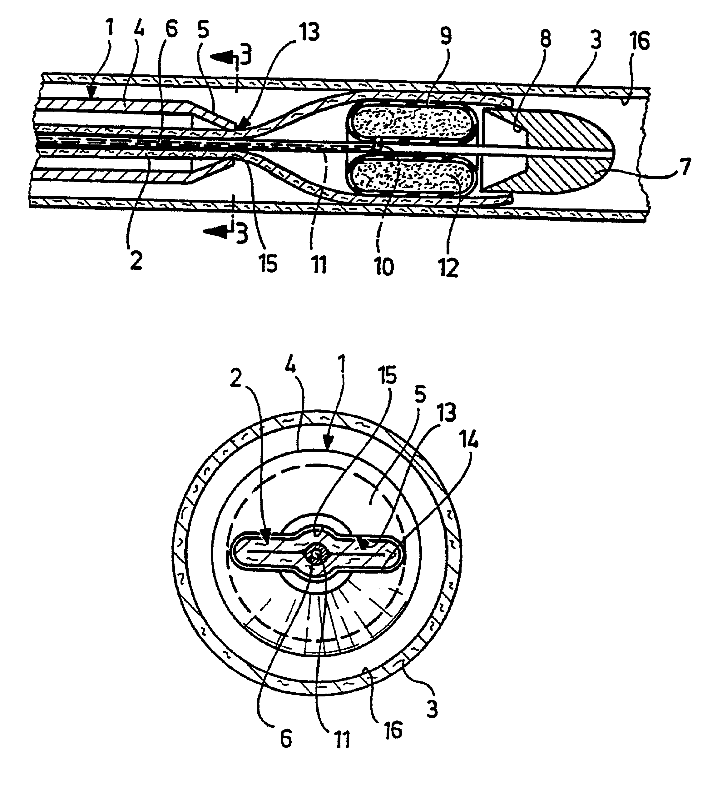
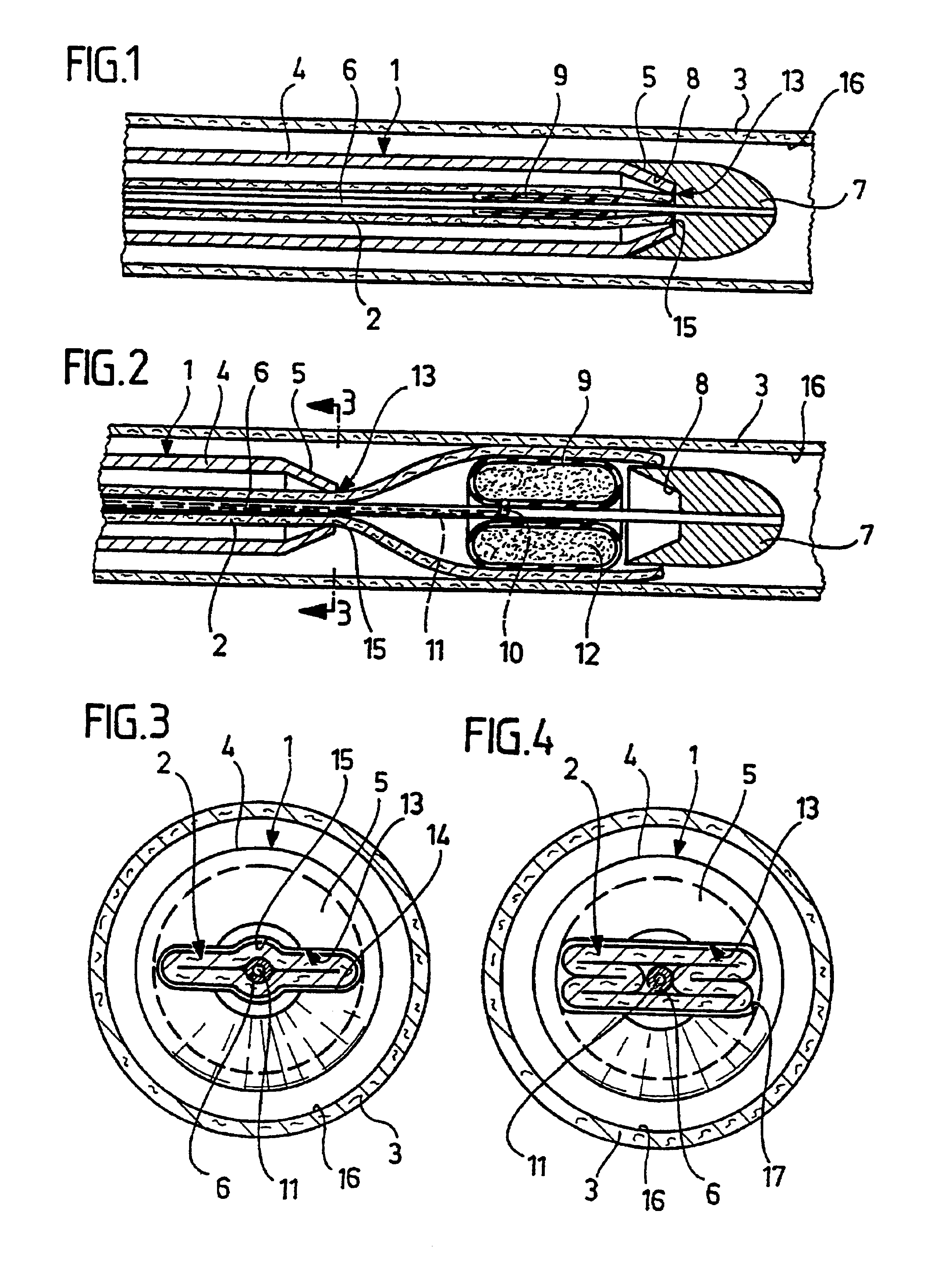
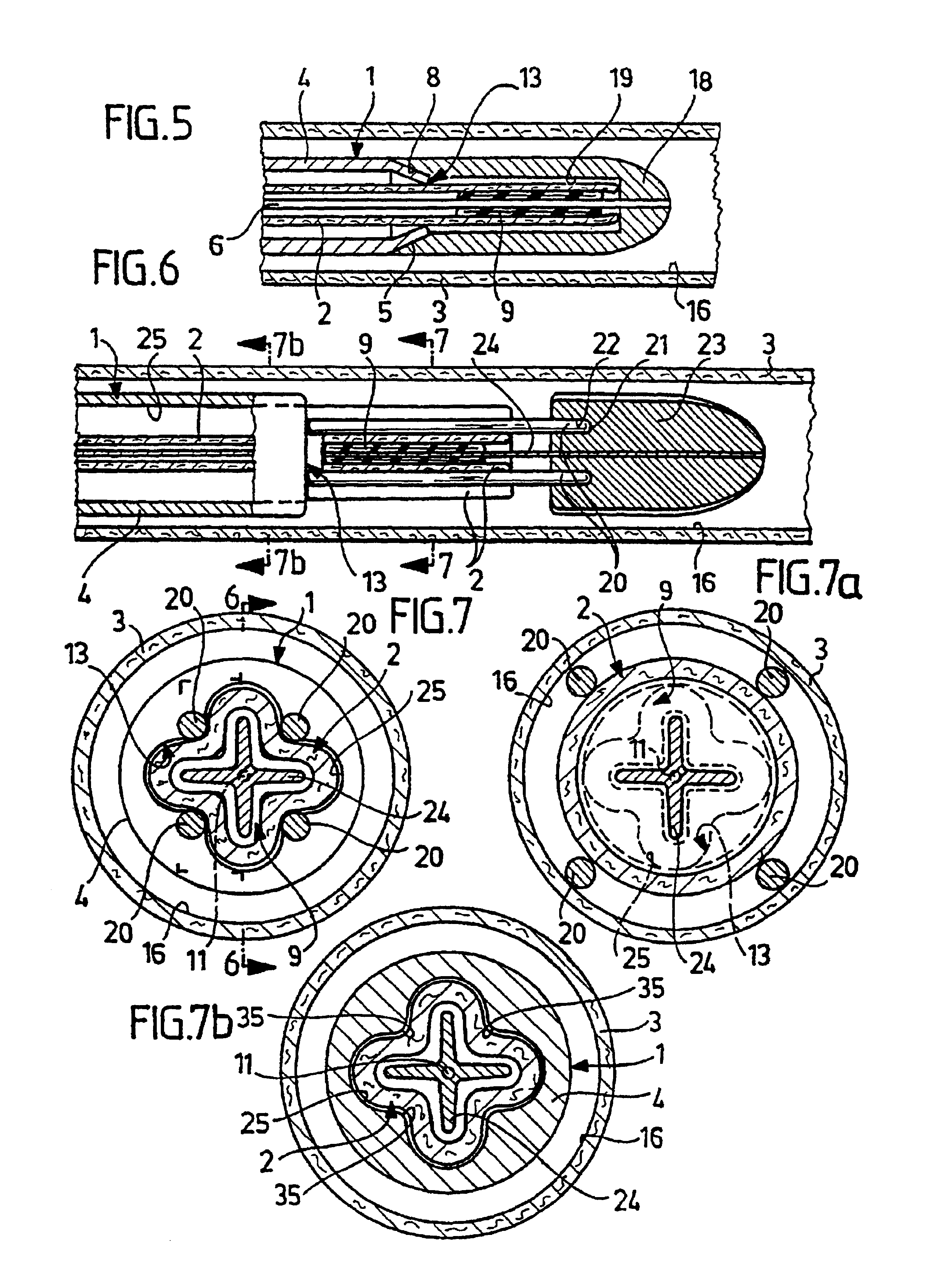
[0072]Several variants of an insertion catheter generally designated 1 for introducing a vascular prosthesis 2 into a vessel 3 are shown in FIGS. 1 to 11. For reasons of clarity, identical parts have the same reference numerals.

[0073]The insertion catheter 1 essentially consists of a tubular catheter cover 4 having a constant cross section over almost its entire length. The catheter cover 4 tapers conically at its distal end so that this end has the shape of an outer cone 5. The wall thickness of the catheter cover 4 is substantially constant over the entire length of the catheter cover 4.

[0074]A guide rod 6 extends through the catheter cover 4 along its axis of symmetry. A guide body 7 is arranged at the distal end of the guide rod 6. The distal end of the guide body 7 is rounded off in the shape of a hemisphere. The proximal end is in the form of an inner cone 8 which is complementary to the outer cone 5 so that the distal end of the catheter cover 4 is insertable with a positive ...


PUM


Abstract

With an insertion catheter for inserting a vascular prosthesis into a vessel, with an elongate, substantially tubular catheter cover having a proximal and a distal end, with an outlet for the vascular prosthesis provided at the distal end, in order to make insertion of the vascular prosthesis into the vessel particularly safe and simple, in particular, to provide the vascular prosthesis with protection against twisting, it is proposed that the outlet have a cross-sectional shape differing from a circular shape, and that the cross-sectional area defined by the outlet area be smaller than the cross-sectional area of the vascular prosthesis inserted in the vessel in the opened, unexpanded state.

Description

[0001]This application is a continuation of international application number PCT / EP00 / 07354 filed on Jul. 29, 2000.[0002]The present disclosure relates to the subject matter disclosed in international application No. PCT / EP00 / 07354 of Jul. 29, 2000, which is incorporated herein by reference in its entirety and for all purposes.BACKGROUND OF THE INVENTION[0003]The invention relates to an insertion catheter for inserting a vascular prosthesis into a vessel, with an elongate, substantially tubular catheter cover having a proximal and a distal end, with an outlet for the vascular prosthesis provided at the distal end.[0004]Vascular supports, i.e., so-called stents or stent grafts comprising metallic supporting structures which may also be covered with fabric are presently in use for treating vascular occlusions in humans, in particular, in the peripheral area of the human body, or also for eliminating abdominal and thoracic aortic aneurysms. These supporting structures are placed endolu...

Claims


Application Information

Patent Timeline
IPC IPC(8): A61F2/06A61M25/00A61M25/06A61F2/95A61M25/12
CPCA61F2/95A61M25/0082A61M25/0068A61M2025/1081A61M25/0662A61M2025/0675
Inventor DWORSCHAK, MANFREDLUTZE, THEODORWEIK, THOMASWEISSHAUPT, DIETERALLENBERG, JENS-RAINER
Owner AESCULAP AG
Why Eureka
Try Eureka