Safety contact mat

a contact mat and safety technology, applied in the field of safety contact mats, can solve the problems of high cost, and achieve the effects of high circuit reliability, simple structural design, and convenient availability

Inactive Publication Date: 2005-05-03
ASO ANTRIEBS UND STEUERUNGSTECHN
View PDF17 Cites 11 Cited by
  • Summary
  • Abstract
  • Description
  • Claims
  • Application Information

AI Technical Summary

Benefits of technology

[0009]Proceeding from this technical background, the objective of the invention is to develop a safety contact mat, which still has...

Problems solved by technology

In addition to the production of safety contact mats with standard dimensions, customers often require custom manufacturing,...

Method used


Image

  • Safety contact mat
  • Safety contact mat
  • Safety contact mat

Examples


Embodiment Construction

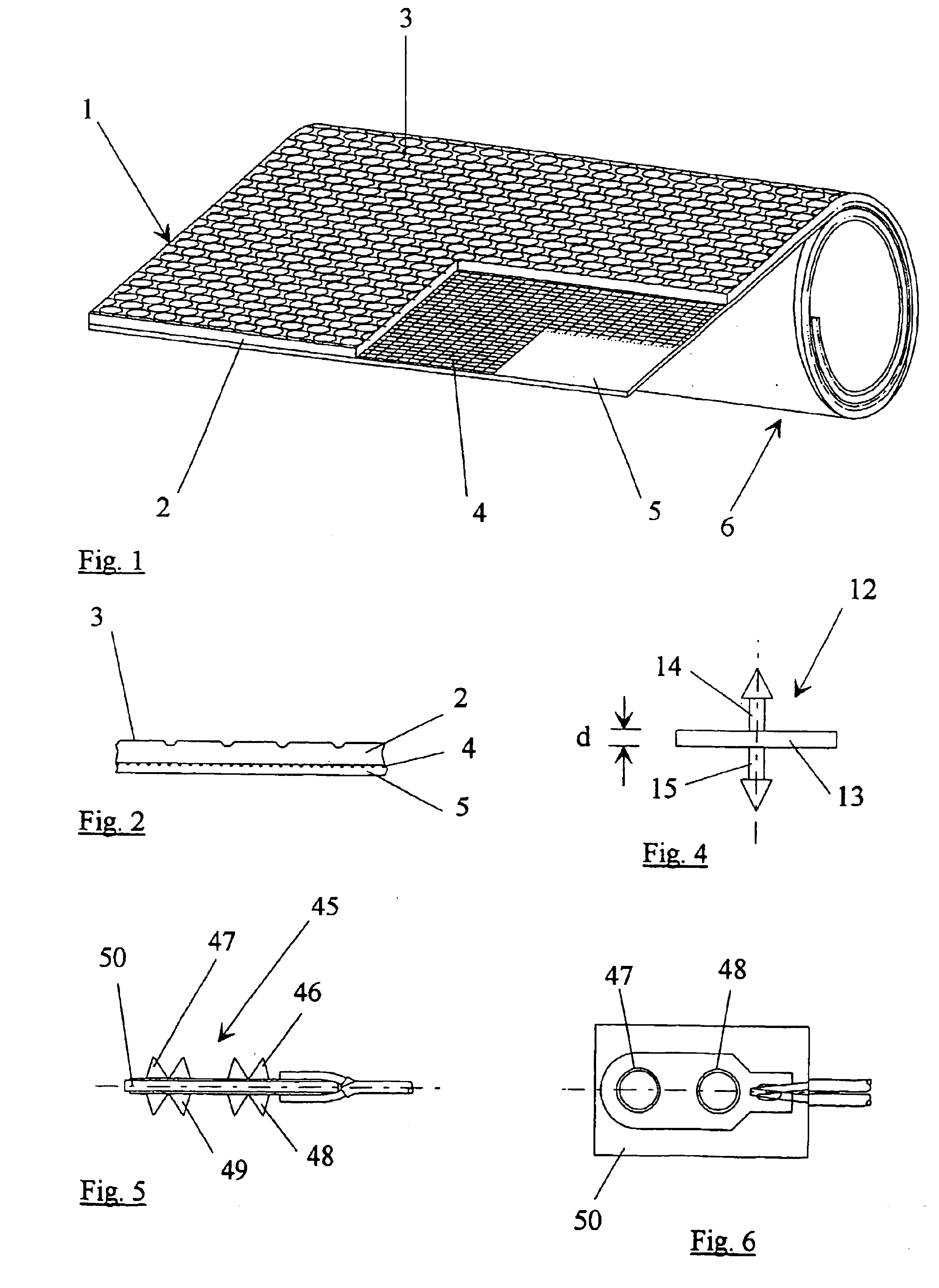
[0045]FIG. 1 shows a flat coextrudate 1, whose uppermost, nonconductive layer is textured by standard means as a running layer 2 with an antislip surface 3.

[0046]An electrically conductive woven material 4 is provided beneath the running layer. This electrically conductive woven material preferably consists of a metal, especially a high-grade steel.

[0047]The running layer 2 is connected with an electrically conductive circuit layer 5 lying beneath it through the woven material 4.

[0048]The running layer 2, the woven material 4, and the circuit layer 5, which consist of different materials throughout, are extruded together, and the flat coextrudate obtained in this way is sufficiently elastic that it can easily be rolled into a roll 6, shipped, and stored. A further advantage in this regard is that the roll width corresponds to the working width.

[0049]The flat coextrudate has an extremely small thickness. For example, the section through the flat coextrudate 1 shown in FIG. 2 is shown...


PUM


Abstract

A safety contact mat has an upper mat half and a lower mat half with respective mutually facing spaced apart conductive layers, which are to be brought into contact in order to close an electrical contact. At least one of the mat halves is formed by a flat coextrudate of a non-conductive elastomer, a conductive elastomer as the conductive layer, and of a conductive woven material enclosed between the elastomers.

Description

PRIORITY CLAIM[0001]This is a U.S. national stage of application No. PCT / DE02 / 02177, filed on 14 Jun. 2002. Priority is claimed on that application and on the following application: Country: Germany, Application No.: 101 29 183.3, Filed: 19 Jun. 2001.BACKGROUND OF THE INVENTION[0002]1. Field of the Invention[0003]The invention concerns a safety contact mat, which has an upper and a lower mat half with two opposing conductive layers spaced some distance apart, which are to be brought into contact to close an electrical contact.[0004]2. Description of the Related Art[0005]Safety contact mats are well known and reliable. They are regularly used for the protection of output areas of machinery or similar hazardous areas that must not be walked on or driven on by persons or vehicles, etc., for safety reasons. Under a weight load, a safety contact mat of this type will, for example, close an electrical circuit, by which an emergency stop of the machinery is effected to prevent injury or da...

Claims


Application Information

Patent Timeline
IPC IPC(8): G08B13/10G08B13/02H01H3/02H01H3/14H01H1/02H01H1/029
CPCG08B13/10H01H3/141H01H2003/147H01H1/029
Inventor FRIEDRICH, HELMUTMEYER, PAUL
Owner ASO ANTRIEBS UND STEUERUNGSTECHN
Why Eureka
Try Eureka