Wind tunnel for a welding power supply housing

a wind tunnel and power supply technology, applied in welding accessories, welding apparatus, manufacturing tools, etc., can solve the problems of heavy particulate flow into the interior of the housing, impractical physical attachment to the circuit board, and increased cooling

Inactive Publication Date: 2005-05-03
ILLINOIS TOOL WORKS INC
View PDF6 Cites 50 Cited by
  • Summary
  • Abstract
  • Description
  • Claims
  • Application Information

AI Technical Summary

Benefits of technology

[0009]The present invention is directed to a wind tunnel for a welding power supply housing that solves the aforementioned problems. The present invention provides a system and method for a welding power supply housing having a wind tunnel extending through the housing to allowing cooling of the various electrical components and at the same time isolates certain electrical components from particulates that may be carried in a cooling flow. Additionally, the present invention allows the heat sink and preferred electrical components to be attached to the circuit board prior to installation of the circuit board within the power supply housing. Upon connecting the circuit board assembly to the power supply housing assembly, the heat sink(s) and / or the preferred electrical components are exposed to the cooling flow within the wind tunnel. The present invention therefore allows exposure of a solder side of the circuit board when the power supply housing cover is removed.
[0014]Therefore, the present invention provides cooling of the electrical components of a welding-type apparatus while maintaining a separation between more sensitive electrical components and those less sensitive, and between the cooling flow within the wind tunnel and the convection cooling within the remainder of the welding-type power supply housing. The present invention also allows for construction of a nearly complete electrical assembly prior to the electrical assembly being mounted within the power supply housing. This configuration therefore allows for the use of wave soldering a majority of the connections of the electrical assembly.

Problems solved by technology

Such air flow creates the additional problem of introducing heavy particulate flow into the interior of the housing.
These components are those components that are also impractical to physically attach to the circuit board and also require more cooling than natural convection can provide.
Although this improved the cooling of the electrical components, it did not address the problem of particulate accumulation to certain electrical components because there was no separation between the cooling flow and the electrical components.
However, these methods increase the complexity of the assembly of the power supply and hinder assembly by preventing assembly of the electrical components of the power supply prior to installation of the electrical assembly within the power supply housing.
This process of partitioning adds to both assembly time and cost.
Additionally, these secondary electrical connections are often made by either hand soldering or using a mechanical means to make the connection because such an assembly is not conducive to wave soldering.
These assemblies also do not provide for the fourth category of electrical components as discussed above.

Method used


Image

  • Wind tunnel for a welding power supply housing
  • Wind tunnel for a welding power supply housing
  • Wind tunnel for a welding power supply housing

Examples


Embodiment Construction

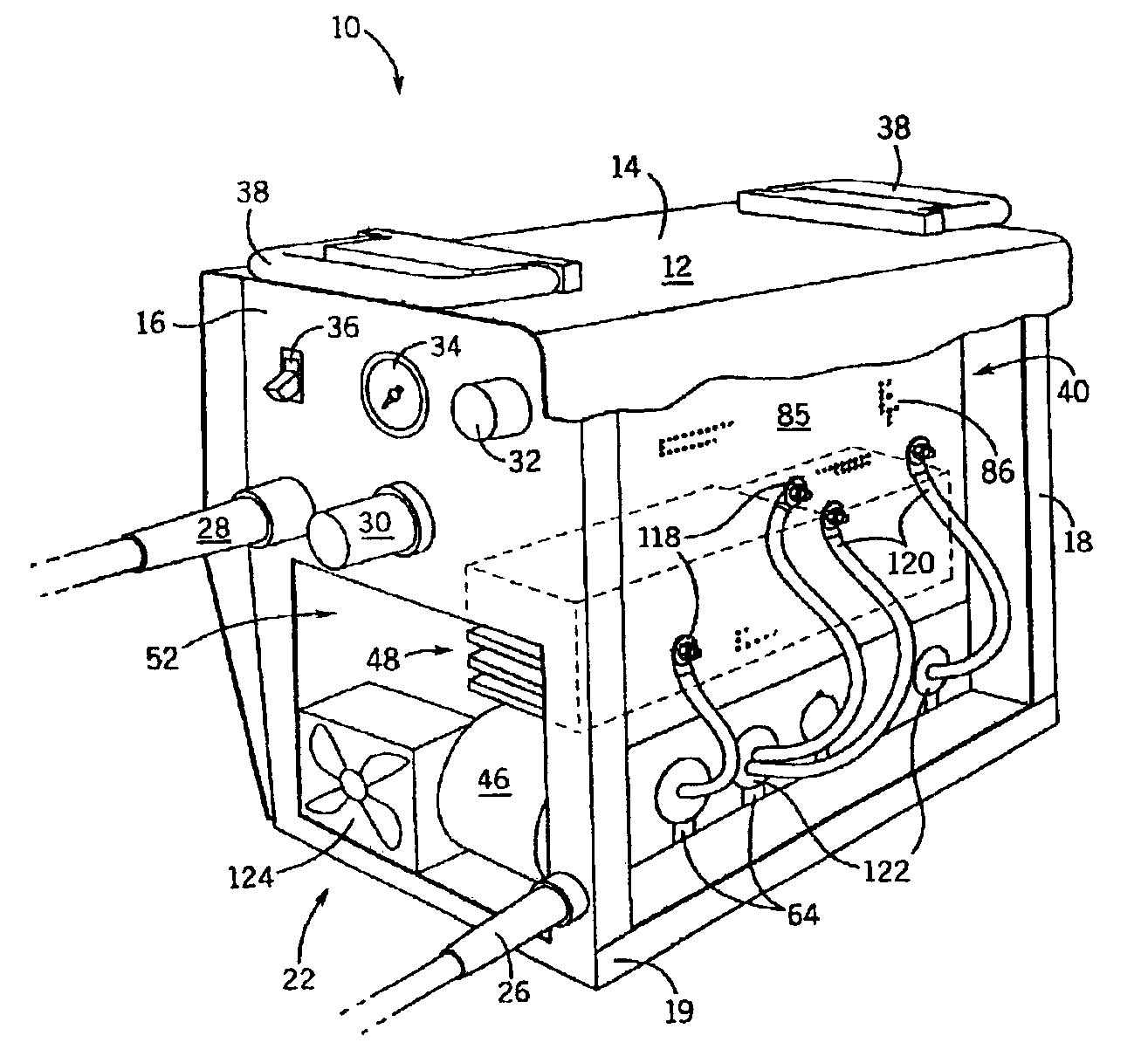
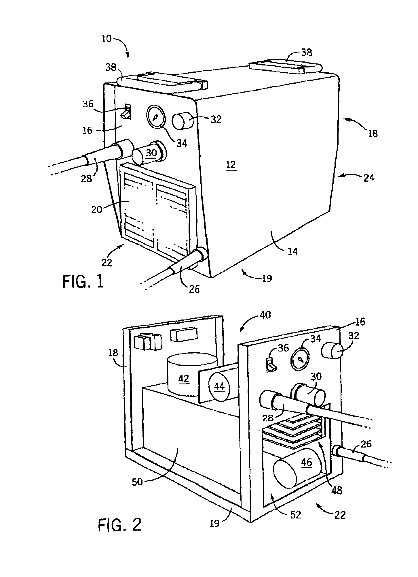
[0025]FIG. 1 shows a power supply 10 having a housing 12. The housing includes a cover 14, a front end panel 16, a rear end panel 18, and a base panel 19. Both the front and rear end panels 16, 18 include louvered openings 20. The end panels 16 and 18 include the louvered openings 20 to allow air to flow from a cooling inlet 22, through the power supply 10, and through a cooling exit 24. The cover 14 is attached to the front end panel 16, the rear end panel 18, and the base panel 19. FIG. 1 also shows: a welding ground lead 26, a welding power lead 28, a control knob 30, a power selector 32, an output gauge 34, and an on / off switch 36; all located in the front end panel 16. A pair of handles 38 is attached to the cover 14 to aid in moving the power supply 10.

[0026]FIG. 2 shows the power supply 10 of FIG. 1 with the cover 14 removed to expose a first chamber 40. First chamber 40 is the space located between the cover 14, the front end panel 16, the rear end panel 18, and the base pan...


PUM

PropertyMeasurementUnit
sizeaaaaaaaaaa
shapeaaaaaaaaaa
durableaaaaaaaaaa

Abstract

A system and method for a welding power supply housing is disclosed. The power supply housing includes a U-shaped panel positioned between two louvered end panels and a base. The combination of the U-shaped panel and the base forms a wind tunnel. The U-shaped panel includes a slot configured to receive a heat sink. The heat sink is in thermal connection with heat generating electrical components of the power supply and is exposed to the cooling flow within the wind tunnel thereby cooling the electrical components of the power supply.

Description

BACKGROUND OF INVENTION[0001]The present invention relates generally to welding systems and, more particularly, to a welding power supply housing assembly having a wind tunnel therein.[0002]Welding power supply housings have a front panel which includes an on / off switch as well as controls such as power adjustment dials and output gauges. Additionally, the housing includes a rear panel and a cover panel. Such welding power supply housings must understandably enclose the entirety of the electrical components.[0003]The housing, being fully enclosed, restricts natural convection cooling of the electronic components required to transform input energy into a desired form. Therefore, louvers are typically constructed into the front and rear panels to accommodate air flow through the housing. Fans have often been incorporated into the assembly of the welding power supply to facilitate improved cooling of the electrical components. Such air flow creates the additional problem of introducing...

Claims


Application Information

Patent Timeline
Patent Type & Authority Patents(United States)
IPC IPC(8): B23K9/32
CPCB23K9/32H05K7/20918
Inventor SCHNEIDER, JOSEPH C.
Owner ILLINOIS TOOL WORKS INC
Why Eureka
Try Eureka