Liquid crystal display device

Inactive Publication Date: 2005-05-03
PANASONIC LIQUID CRYSTAL DISPLAY CO LTD +1
View PDF8 Cites 56 Cited by
  • Summary
  • Abstract
  • Description
  • Claims
  • Application Information

AI Technical Summary

Benefits of technology

[0011]In the liquid crystal display device having the above-described construction, even if leakage current due to scanning or video signals flo

Problems solved by technology

For this reason, it has been found, when the liquid crystal display device is being driven by an external circuit, part of the video signals from the video signal lines flow into the static protection elements as leakage

Method used


Image

  • Liquid crystal display device
  • Liquid crystal display device
  • Liquid crystal display device

Examples


Embodiment Construction

[0017]Embodiments of the liquid crystal display device according to the present invention will be described below with reference to the accompanying drawings.

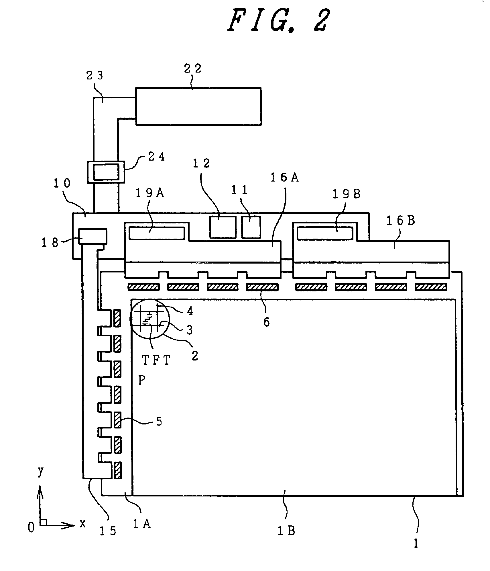
[0018]FIG. 2 is a schematic view showing the construction of the entire liquid crystal display device according to the present invention. In this embodiment, the present invention is applied to a liquid crystal display device which adopts a so-called in-plane field mode of operation, which is known to have a wide viewing angle.

[0019]A liquid crystal display panel 1 includes transparent substrates 1A and 1B which are arranged opposite to each other across a liquid crystal and serve as a package. One of these transparent substrates (the lower substrate shown in FIG. 2, i.e. a transparent matrix substrate 1A) is formed to be slightly larger than the other transparent substrate (the upper substrate shown in FIG. 2, i.e. a transparent color filter substrate 1B), and both transparent substrates are arranged to be nearly even with eac...


PUM


Abstract

A liquid crystal display device having a first substrate, a second substrate, a liquid crystal layer interposed between the first substrate and the second substrate, a plurality of video signal lines and scanning signal lines formed on the first substrate, and defining pixel regions, a thin film transistor formed in the pixel regions, and driven by a scanning signal from the scanning signal line for supplying video signal from one of the video signal lines to a pixel electrode and a display area containing a plurality of the pixel regions. A first protection element line formed at a peripheral portion of the display area, and being connected to a odd-numbered ones of the video signal lines by first high-resistance elements, and a second protection element line formed at a peripheral portion of the display area, and being connected to even-numbered ones of the video signal lines by second high-resistance elements.

Description

CROSS-REFERENCE TO RELATED APPLICATION[0001]This application is a continuation of U.S. application Ser. No. 09 / 973,775, filed Oct. 11, 2001, now U.S. Pat. No. 6,710,824, which is a continuation of application Ser. No. 09 / 342,131 filed on Jun. 29, 1999, now U.S. Pat. No. 6,333,769, the contents of which are incorporated herein by reference in their entirety.BACKGROUND OF THE INVENTION[0002]The present invention relates to a liquid crystal display device; and, more specifically, the invention relates to an in-plane field type liquid crystal display device.[0003]In general, an in-plane field type liquid crystal display device is provided with a pixel electrode and a counter electrode spaced apart from the pixel electrode in each pixel area on a liquid-crystal-side surface of one of the transparent substrates which are opposed to each other via a liquid crystal, and the optical transmittance of the liquid crystal is controlled by means of an electric field which is selectively generated...

Claims


Application Information

Patent Timeline
IPC IPC(8): G02F1/13G02F1/1362G02F1/1345G02F1/1343G02F1/136G02F1/1368
CPCG02F1/136204G02F1/1345G02F1/1343
Inventor SUZUKI, NOBUYUKIORITSUKI, RYOJINAKANO, YASUSHI
Owner PANASONIC LIQUID CRYSTAL DISPLAY CO LTD
Why Eureka
Try Eureka