
Antenna coupling systems and methods for transmitters

a technology of antenna coupling and transmitter, applied in the direction of antenna, antenna, amplifier, etc., can solve the problems of combiners wasting significant energy as heat, difficult to couple the outputs of power amplifiers and difficult to couple a plurality of radio channel frequency signals to a common antenna without appreciable loss

Inactive Publication Date: 2005-05-03
ERICSSON INC
View PDF40 Cites 126 Cited by
  • Summary
  • Abstract
  • Description
  • Claims
  • Application Information

AI Technical Summary

Benefits of technology

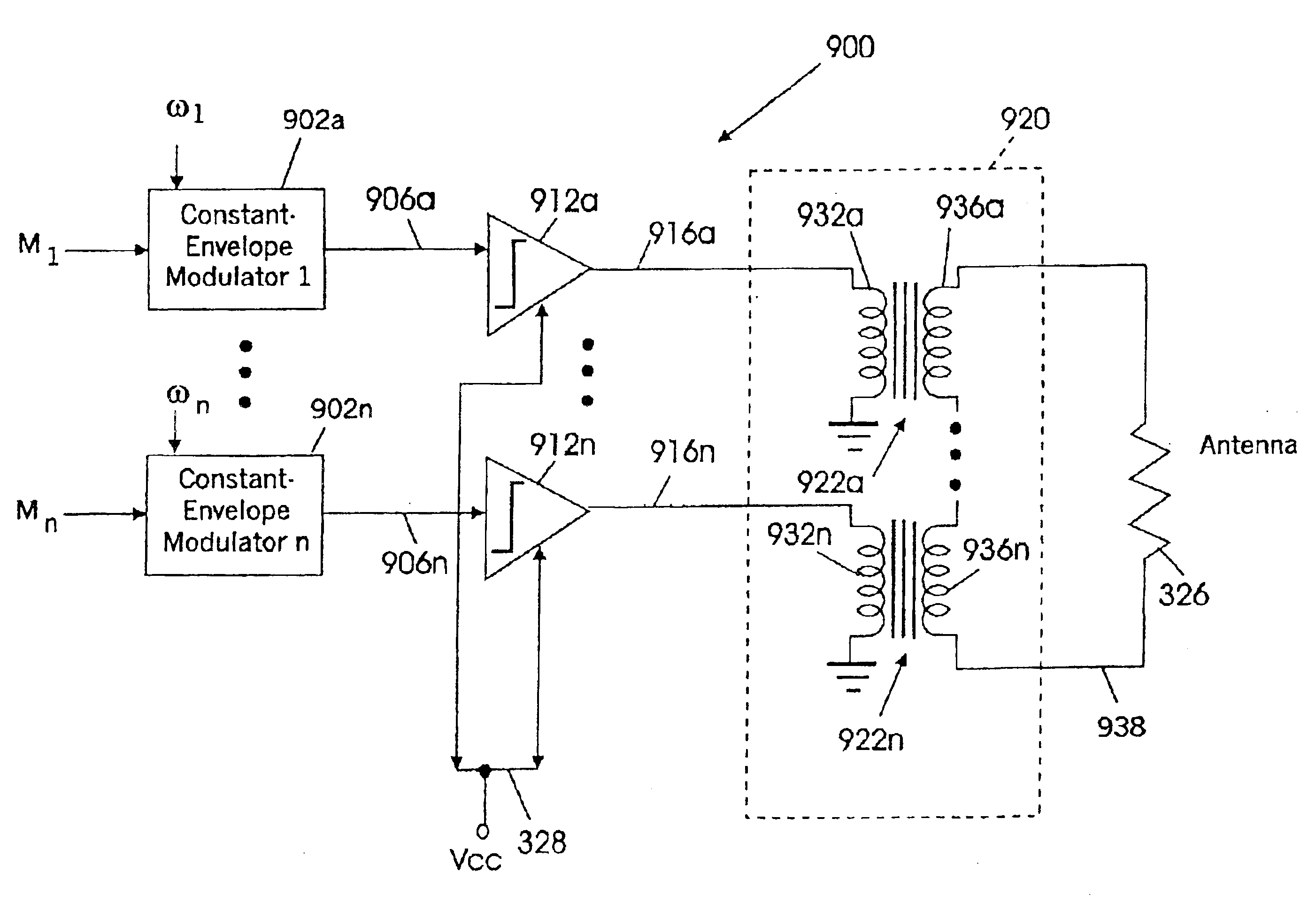
[0078]In conclusion, the present invention can extend the efficiency advantages of series-coupled transmitter power amplifier configurations to applications that use several transmitters operating on different radio channels to share the same antenna, such as a radiotelephone base station. Other single-carrier transmitters may be combined using the present invention to produce a multi-carrier transmitter, such as the quadrature power digital-to-analog converter techniques of U.S. patent application Ser. No. 09 / 208,912, filed Dec. 10, 1998 entitled Systems and Methods for Converting a Stream of Complex Numbers Into a Modulated Radio Power Signal to the present inventor et al.; and U.S. patent application Ser. No. 09 / 216,466, filed Dec. 18, 1998 entitled Systems and Methods for Converting a Stream of Complex Numbers Into An Amplitude and Phase-Modulated Radio Power Signal to Holden et al., both of which are assigned to the assignee of the present invention, the disclosures of both of which are hereby incorporated by reference herein.

Problems solved by technology

Unfortunately, it may be difficult to couple a plurality of a radio channel frequency signals to a common antenna without appreciable loss.
In particular, the radio channel frequency signals generally are amplified by a respective plurality of power amplifiers, and it may be difficult to couple the outputs of the power amplifiers to a common antenna without appreciable loss.
Unfortunately, these combiners may waste significant energy as heat, and / or may not be selective enough to allow adjacent channels to be combined unless they use cooled, superconductive resonators.

Method used


Image

  • Antenna coupling systems and methods for transmitters
  • Antenna coupling systems and methods for transmitters
  • Antenna coupling systems and methods for transmitters

Examples


Embodiment Construction

[0020]The present invention now will be described more fully hereinafter with reference to the accompanying drawings, in which preferred embodiments of the invention are shown. This invention may, however, be embodied in many different forms and should not be construed as limited to the embodiments set forth herein; rather, these embodiments are provided so that this disclosure will be thorough and complete, and will fully convey the scope of the invention to those skilled in the art. Like numbers refer to like elements throughout. It will be understood that when an element is referred to as being “connected” or “coupled” to another element, it can be directly connected or coupled to the other element or intervening elements may be present. In contrast, when an element is referred to as being “directly connected” or “directly coupled” to another element, there are not intervening elements present. Moreover, each embodiment described and illustrated herein includes its complementary ...


PUM


Abstract

Multiple radio channel frequency signals that are modulated with respective information modulation are transmitted from a common antenna at multiple radio frequencies. Multiple modulators are provided, a respective one of which corresponds to a respective one of the radio channel frequencies. Each modulator generates at least one constant amplitude, phase modulated drive signal at the corresponding radio channel frequency from the respective information modulation, such that the at least one constant amplitude, phase modulated drive signal corresponds to the information modulation for the corresponding radio frequency. At least one saturated power amplifier is provided for each of the at least one constant amplitude, phase modulated drive signals. A respective saturated power amplifier is responsive to the corresponding constant amplitude, phase modulated drive signal, to produce a corresponding amplified output signal at an output thereof. A coupling network connects the outputs of the saturated power amplifiers in series, to produce a combined signal that is applied to the common antenna, such that the common antenna radiates the radio channel frequency signals that are modulated with the respective information modulation. In first embodiments, the at least one constant amplitude, phase modulated drive signal is a single constant envelope modulation drive signal, wherein the information modulation is a constant envelope information modulation. In other embodiments, at least two constant amplitude phase modulated drive signals are provided at the corresponding radio channel frequency, such that the at least two constant amplitude, phase modulated drive signals correspond to the information modulation for the corresponding radio frequency.

Description

CROSS REFERENCE TO RELATED APPLICATIONS[0001]This application is a Continuation-in-Part (CIP) of application Ser. No. 09 / 209,104, filed Dec. 10, 1998 now U.S. Pat. No. 6,311,046, entitled “Linear Amplification Systems and Methods Using More Than Two Constant Length Vectors” to the present inventor, assigned to the assignee of the present invention, which itself is a CIP of application Ser. No. 09 / 054,063, filed Apr. 2, 1998 now U.S. Pat. No. 6,133,788, entitled “Hybrid Chireix / Doherty Amplifiers and Methods” to the present inventor, assigned to the assignee of the present invention. This application also is a CIP of application Ser. No. 09 / 361,080, filed Jul. 26, 1999 now U.S. Pat. No. 6,097,615, entitled “Power Waveform Synthesis Using Bilateral Devices” to the present inventor, assigned to the assignee of the present invention, which itself is a continuation of application Ser. No. 09 / 054,060 filed Apr. 2, 1998 of the same title, now U.S. Pat. No. 5,930,128. The disclosures of all...

Claims


Application Information

Patent Timeline
IPC IPC(8): H01Q11/12H01Q11/00H04B1/02H04B1/44H01Q5/00H01Q5/50
CPCH01Q5/50H04B1/0458H03F1/0294
Inventor DENT, PAUL WILKINSON
Owner ERICSSON INC
Learn More