
Cosmetic container with spring-biased mirror

a mirror and cosmetics technology, applied in the field of compact cases with mirrors, can solve the problems of increasing the likelihood of accidental opening of the mirror, clumsy closing operation, and requiring manual dexterity of fingers, and achieve the effect of reducing the probability of the mirror being accidentally released

Inactive Publication Date: 2005-05-10
HCT GRP HLDG LTD
View PDF18 Cites 29 Cited by
  • Summary
  • Abstract
  • Description
  • Claims
  • Application Information

AI Technical Summary

Benefits of technology

[0006]It is an object of the present invention to overcome the problems of the prior art by providing a compact case with a spring-biased mirror which provides a simple means for securing the mirror in its closed, concealed position.
[0007]It is a further object of the present invention to eliminate the projection of any securing means outside of the cosmetic case to reduce the likelihood of the mirror being accidentally released to its exposed position.
[0008]It is yet another object of the present invention to eliminate any large openings within the cosmetic case when the mirror is in its closed, concealed position which might serve as a conduit for the entry of dirt into the spring mechanism.
[0009]It is still yet a further object of the present invention to provide a cosmetic case with a spring-biased mirror wherein the user can access the cosmetic without triggering the mirror to move into its exposed position.
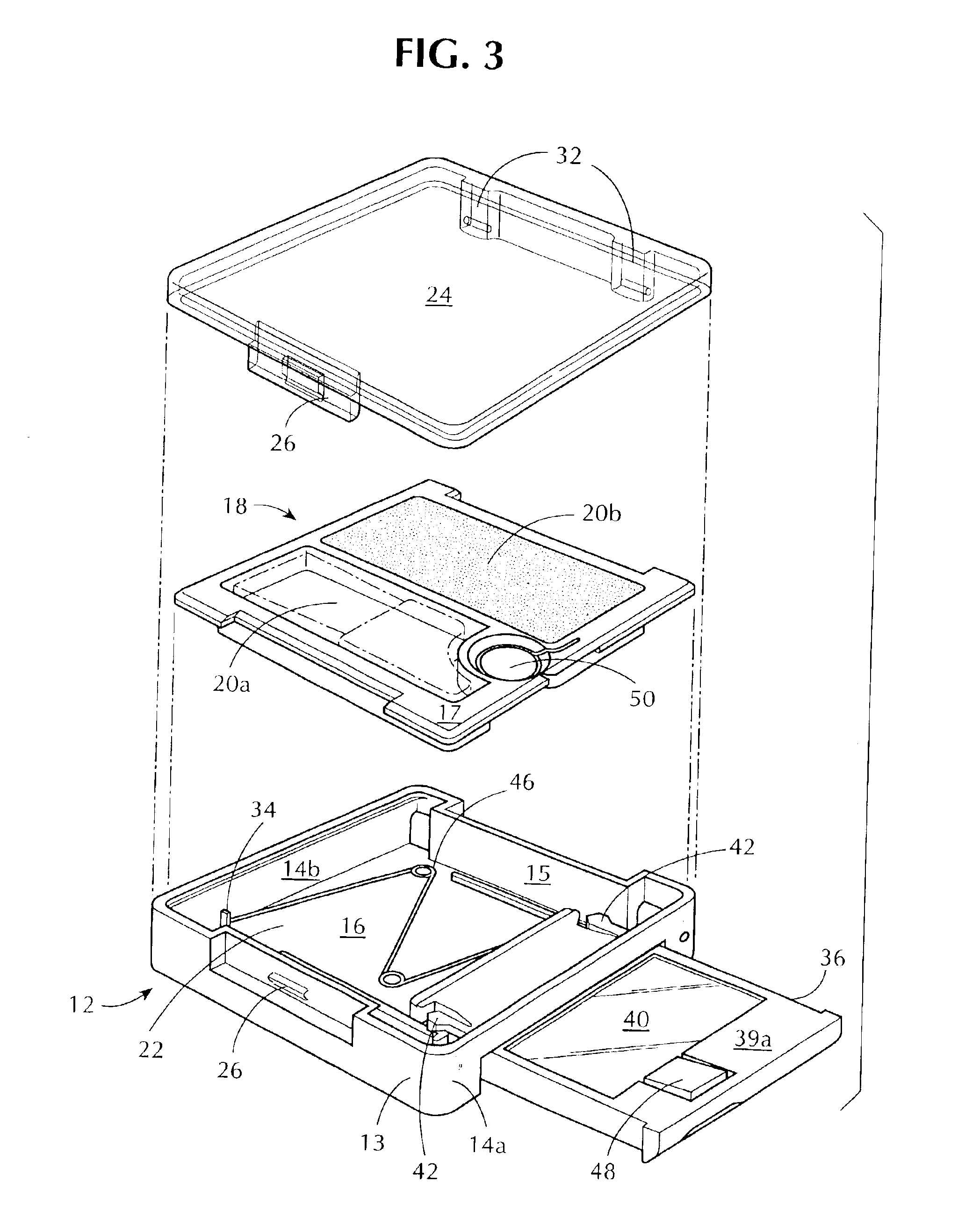
[0010]These and other objects of the invention are met by the invention disclosed herein. The cosmetic case comprises a generally square-shaped base fabricated preferably of plastic having an upper compartment or tray containing one or more receptacles for the storage of cosmetics, such as blush, and an applicator brush. Directly beneath the tray is disposed a lower compartment within the base wherein resides a mirror supported within a mirror frame. The mirror frame is attached at one of its ends to one or more compression springs which are attached to a side wall of the lower compartment. The mirror frame rests between a substantially parallel pair of guide tracks protruding from the bottom wall of the lower compartment. Integrally molded on opposed sides of the mirror frame are a pair of stop tabs. These stop tabs serve to prevent the mirror frame from being completely ejected outside of the lower compartment by the action of the spring.
[0012]Hingedly attached to the base is a cover, preferably of transparent plastic, which in its closed position fits over the base and protects the cosmetics contained within the receptacles of the tray from exposure to dirt, dust and precipitation and, in its open position, provides ready access to the cosmetics by the user.

Problems solved by technology

One drawback of this invention is that the closing operation is clumsy and requires manual dexterity of the fingers which many older users of the compact may lack.
Additionally, the appearance of a slot in and across almost the entirety of the width of the back of the case, with the locking member protruding there though, is unsightly and presents a means by which dirt or grit may enter the bottom of the compact and impair the operation of the slidable mirror.
This slot also allows for snagging of the locking member on other articles within a purse or pocket thus increasing the likelihood of an accidental opening of the mirror.
Thus, the user is unable to return the mirror to its closed position if the user desires to continue to use the lipstick holder by itself.
Thus, the user cannot use the lipstick alone without the mirror being projected out, even if the mirror is not desired to be used.

Method used


Image

  • Cosmetic container with spring-biased mirror
  • Cosmetic container with spring-biased mirror
  • Cosmetic container with spring-biased mirror

Examples


Embodiment Construction

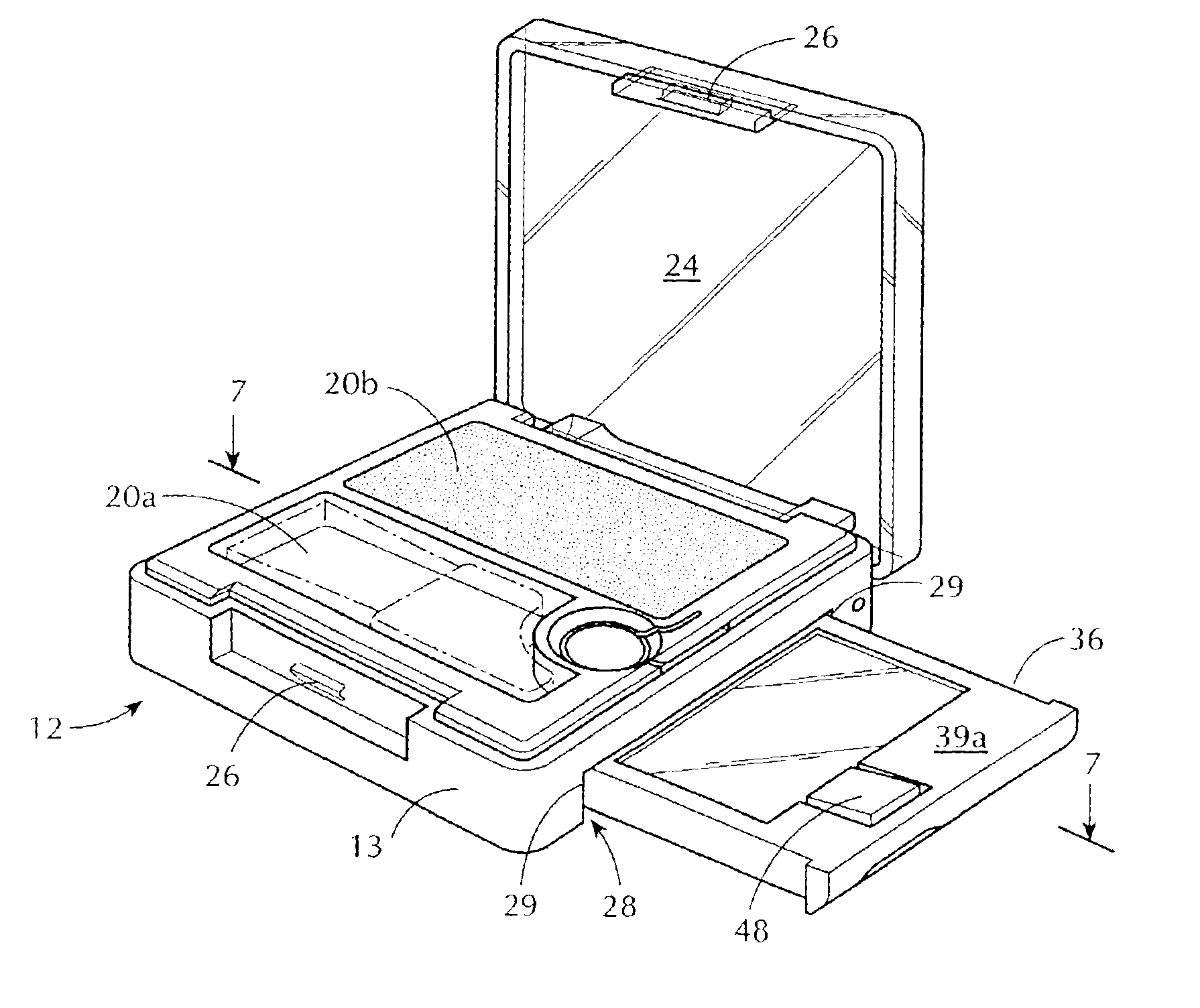
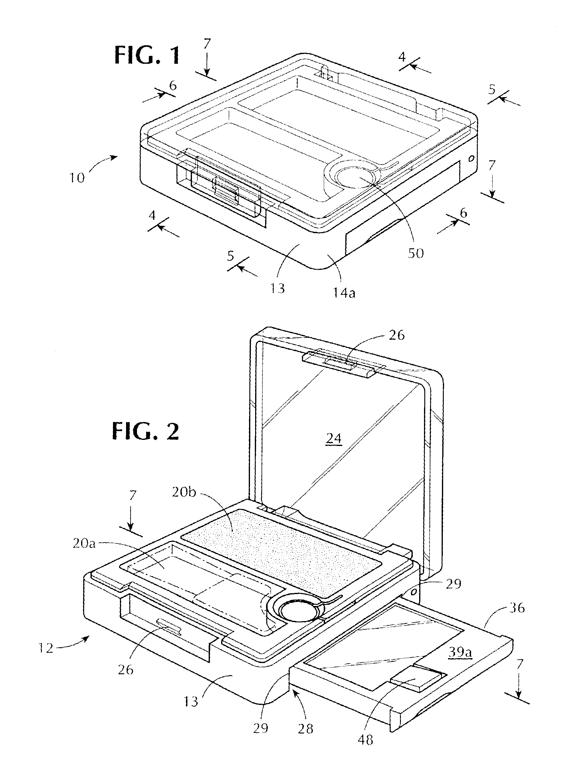
[0027]Referring now to the drawings there is shown in FIGS. 1, 2 and 3 a cosmetic container with spring-biased mirror. The cosmetic container 10 includes a preferably generally square-shaped base 12 having a front wall 13, two sidewalls 14a, 14b, a rear wall 15 and a bottom wall 16. Overlaying base 12 is a tray 18 having one or more receptacles 20a, 20b disposed therein for the storage of cosmetics and an applicator brush. The bottom wall 16 is in contact with and connected to front wall 13, each of the sidewalls 14, and the rear wall 15. The front, rear and side walls are also in contact with and connected to the tray 18 to form a lower compartment 22 within base 12. A generally square-shaped lid 24 is hingedly attached to the rear wall 15. The lid 24 and the front wall 13 are provided with mating locking elements 26 of conventional design for effectuating the closure of the lid 24 of the compact 10. It will be understood by those of ordinary skill in the art that the shape of the ...


PUM


Abstract

A cosmetic container with spring-biased mirror is provided. The cosmetic container has a lower compartment containing a mirror frame and mirror concealed within. The mirror frame is held in place against the force of the spring by a first flexible hinge which abuts a sidewall of the lower compartment. When the user desires to access the mirror, they press downwards upon a second flexible hinge in the tray of the container which holds the cosmetic. The flexible hinge in the tray is in relationship with the flexible hinge in the mirror frame. Thus, a downwards force applied to the flexible hinge in the tray transmits the downward force to the flexible hinge in the mirror frame. This force disengages the flexible hinge in the mirror frame from the sidewall of the lower compartment, thus permitting the spring to urge the mirror frame and mirror from their concealed position to their exposed position where the mirror is available for use.

Description

BACKGROUND OF THE INVENTION[0001]The present invention relates generally to a compact case for cosmetics. More particularly, the invention relates to a compact case having a spring-biased mirror within its base, the mirror in its closed position being concealed within the base and out of communication with the cosmetic powder held within the receptacles of a tray overlaying the base. In operation, the user opens the lid of the compact overlaying the tray and depresses a flexible latch within the tray whereupon the mirror is projected by a spring to an exposed position outside of the base of the compact where it is readily available for access by the user.[0002]Cosmetic holding cases or compacts with manually slidable or movable mirrors are known in the art. U.S. Pat. No. 2,205,974 to Kramer discloses a cosmetic holding device wherein the mirror is contained within the case and is slidable out of the interior of the case from its normally concealed position to a position where it can...

Claims


Application Information

Patent Timeline
Patent Type & Authority Patents(United States)
IPC IPC(8): A45D33/20A45D33/00A45D40/00A45D40/22
CPCA45D33/008A45D33/20B29L2031/3014A45D40/22
Inventor THORPE, TIMOTHYRODRIGUEZ, JACK
Owner HCT GRP HLDG LTD
Learn More