Latent heat storage device

Inactive Publication Date: 2005-05-10
MODINE MFG CO
View PDF25 Cites 40 Cited by
  • Summary
  • Abstract
  • Description
  • Claims
  • Application Information

AI Technical Summary

Benefits of technology

[0012]It is the principal object of the invention to provide a new and improved latent heat storage device. More specifically, it is an object of the invention to provide a latent heat storage device that is ideally sui

Problems solved by technology

Consequently, there is a limited amount of space available for the heat battery.
Generally, merely reducing the size of the latent heat battery is not a sufficient response to the problem.
Reducing the size of the battery also reduces its capacity to store heat in that, as the volume of the latent heat battery is reduced, the quantity of PCM that it can accommodate is concomitantly reduced, thereby reducing its heat capacity.
Furthermore, since the coolant flowing through the salt jacket is under pressure, a large pressure differential between the inside and outside of the salt jacket is created, causing the salt jacket to tend to deflect outward.
Similarly, the outer jacket has a nominal pressure on the outside of one atmosphere and vacuum on the inside, causing the outer jacket to tend to deflect inward.
This reduces the insulating ability of the insulating space.
Further, as the salt jacket deforms, it in turn may deform the PCM container(s) contained in the salt jacket.
Furthermore, every time the vehicle is operated the coolant pressure oscillates between one and two atmospheres as the vehicle heats up.
This results in a fatigue cycle being imposed on the PCM container(s

Method used


Image

  • Latent heat storage device
  • Latent heat storage device
  • Latent heat storage device

Examples


Embodiment Construction

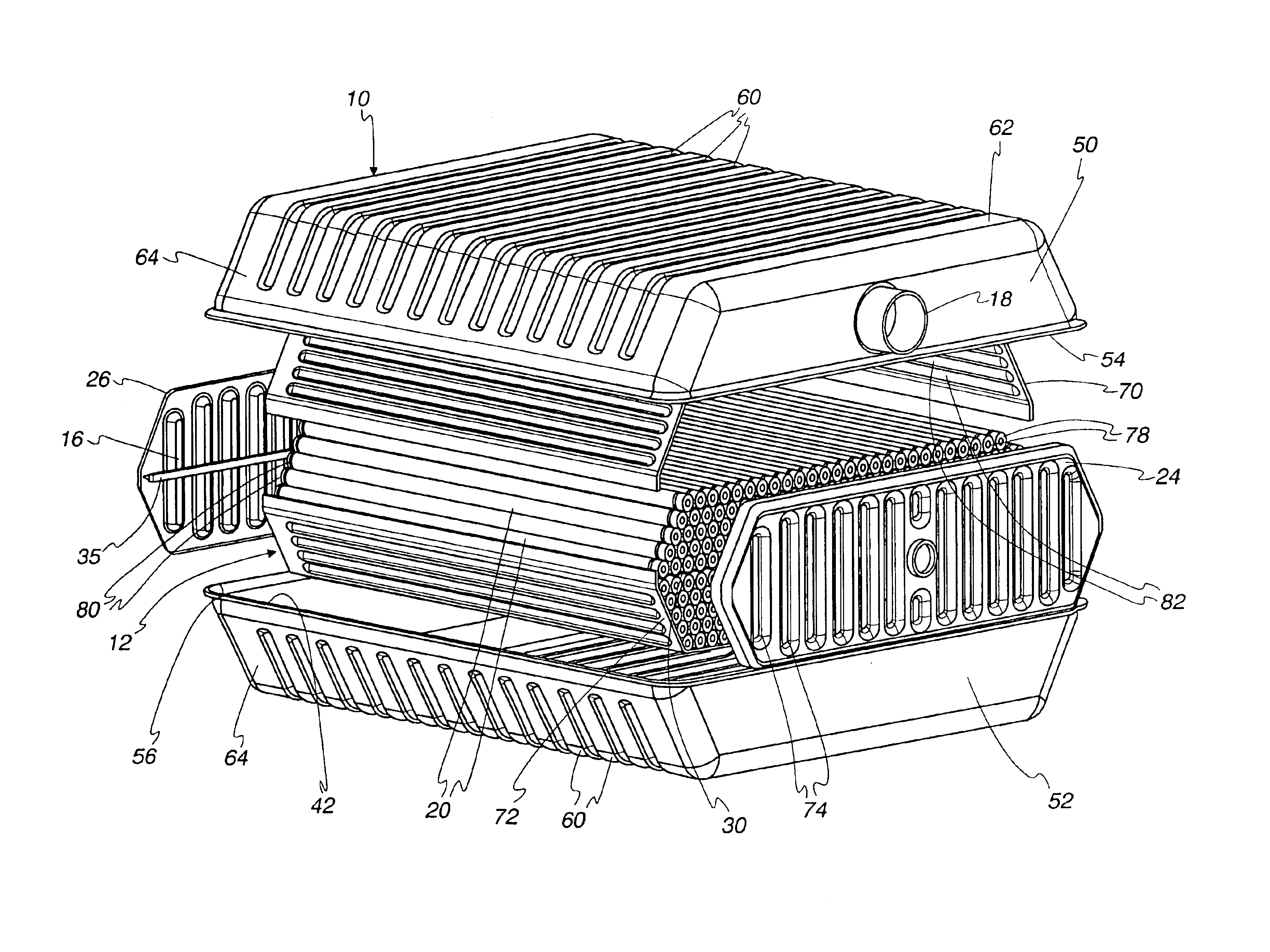
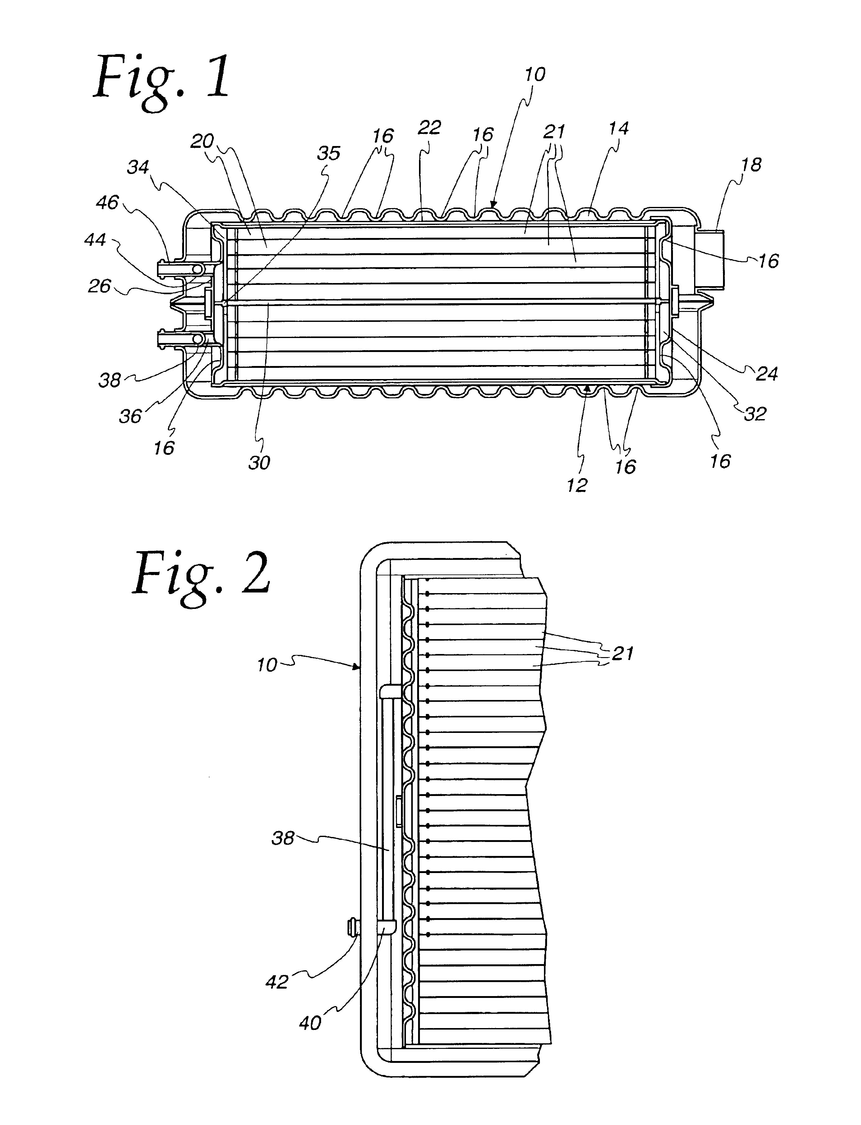
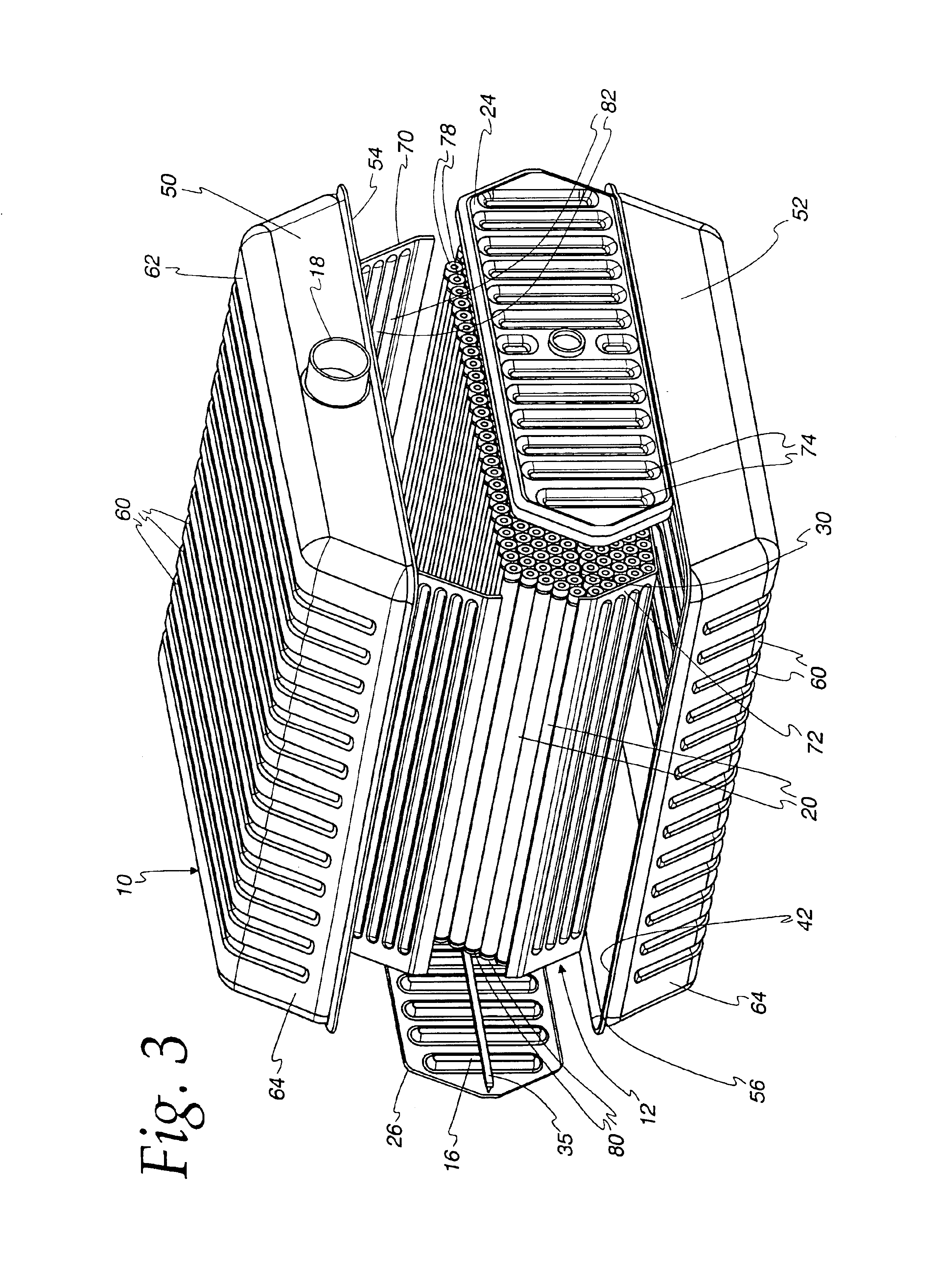
[0033]Referring to FIGS. 1 and 2, a latent heat storage device made according to the invention is illustrated. The same will be described in the context of a vehicular application but it is to be understood that except as insofar as restricted by the appended claims, the same will find application in other uses as well.

[0034]The latent heat storage device includes an outer jacket, generally designated 10, which surrounds a salt case or jacket, generally designated 12. The outer jacket 10 is optional but will be employed when the latent heat storage device is used as heat battery. It is spaced from the salt case 12 so as to define an insulating space 14. A plurality of conventional stand-offs 16 extend between the outer jacket 10 and the salt case 12 to provide the desired spacing. The stand-offs are preferably made of a material with poor thermal conductivity.

[0035]In the usual case, the space 14 will be subject to a vacuum which may be pulled through a port 18. At the same time, su...


PUM


Abstract

A low volume, high capacity latent heat storage device is achieved in a construction including a salt case (12) with an optional outer jacket (10) surrounding the salt case (12) in spaced relation thereto to define an insulating space (14) between the two. Inlet and outlet conduits (38), (42), (44), (46), extend from the exterior of the outer jacket (10) to the interior of the salt case (12) and at least one tube (20) is located within the salt case and has a plurality of straight, parallel runs (21) defining a matrix with an exterior and a phase change material is sealed within the tube (20). The tube runs (21) inwardly of the matrix exterior are in a regular or equilateral polygonal pattern with each run (21) abutting a plurality of adjacent runs (21) and each run (21) at the exterior of the matrix additionally engaging the salt jacket (12). The runs (21) have cross-sectional shapes such that flow spaces (102, (104) exist between the runs (21) and between the salt jacket (12) as well between adjacent runs (21). The flow spaces (102), (104) are in fluid communication with the inlet and outlet conduits (38), (42), (44), (46).

Description

FIELD OF THE INVENTION[0001]This invention relates to latent heat storage devices, and more particularly, to a relatively small volume latent heat storage device with a high heat storage capacity.BACKGROUND OF THE INVENTION[0002]Recent years have seen an increasing demand for latent heat storage devices, particularly in vehicular applications where they are employed as latent heat batteries. A typical latent heat battery typically includes one or more containers of a phase change material (PCM). The PCM absorbs and releases energy in the form of sensible and latent heats, as the material is heated or cooled and / or changes phases between liquid and solid in the heating or cooling process. A typical source of heat is the coolant from a vehicle engine which is flowed about the container of phase change material. When the latent heat battery is charged, the phase change material will be in the liquid phase. Consequently, if cold coolant is circulated about the container of phase change ...

Claims


Application Information

Patent Timeline
IPC IPC(8): F28D20/02B60H1/00
CPCB60H1/00492F28D20/02Y10S165/906Y10S165/902Y02E60/145Y02E60/14
Inventor LUKAS, HENRYGASPER, CHARLES G.LOGIC, JEFFREY A.LARRABEE, SCOTT R.ROGERS, C. JAMESVOSS, MARK G.MEISSNER, ALAN P.FIETKIEWICZ, B. JOSEPH
Owner MODINE MFG CO
Why Eureka
Try Eureka