Redirecting device for a conveying means located on a conveying section

a technology of turning device and conveying section, which is applied in the direction of transportation and packaging, conveyor parts, rollers, etc., can solve the problems of compact design of the turning device having a semi-circular-shaped turning element, and achieve the elimination of costly disassembly and/or disassembly of the transport line, and reduce the assembly cost of the turning element. , the effect of reducing the assembly cos

Inactive Publication Date: 2005-05-10
ROBERT BOSCH GMBH
View PDF13 Cites 11 Cited by
  • Summary
  • Abstract
  • Description
  • Claims
  • Application Information

AI Technical Summary

Benefits of technology

[0003]In contrast, the turning device according to the invention for a conveyance means on a transfer line has the advantage that very little assembly work is required when repairing or maintaining the conveyance means, since costly dismantling and / or disassembly of the transport lines can be eliminated when transport lines are situated next to each other. This is attained by means of the invention by the fact that the turning element, including the conveyance means, is capable of being guided into the housing of the turning device from above. Access through the side of the turning device is therefore no longer required.
[0004]Additional advantageous further developments of the turning device according to the invention for a conveyance means on a transport line result from the dependent claims. In order to also reduce the assembly expense of the turning element, it is particularly advantageous to provide guides and / or recesses in the housing, into which the turning element is capable of being inserted with positive engagement. By using hold-down devices located on the cover, the turning element need not be mounted and / or immobilized in the housing. This function is performed simultaneously by the cover that immobilizes the turning element in the housing with positive engagement. The cover with integrated hold-down function can be realized particularly easily and cost-effectively when the cover is designed together with the hold-down devices as a one-piece component. In contrast to the turn-around rollers, turn-around cylinders, etc., known in the related art, the turning element itself can be produced particularly cost-effectively when it is composed of plastic. The conveyance means then turns around directly, i.e., in contact with the turning element. Forming the turning element out of plastic also makes it possible—in a particularly advantageous exemplary embodiment—to design the turning element substantially semicircular in shape. As a result, in contrast to the known turn-around rollers, turn-around cylinders, etc., installation space equivalent to approximately half of the diameter of a turn-around roller and / or turn-around cylinder is spared. As a result, the design of the turning device having a semicircular-shaped turning element is particularly compact.

Problems solved by technology

As a result, the design of the turning device having a semicircular-shaped turning element is particularly compact.

Method used


Image

  • Redirecting device for a conveying means located on a conveying section
  • Redirecting device for a conveying means located on a conveying section
  • Redirecting device for a conveying means located on a conveying section

Examples


Embodiment Construction

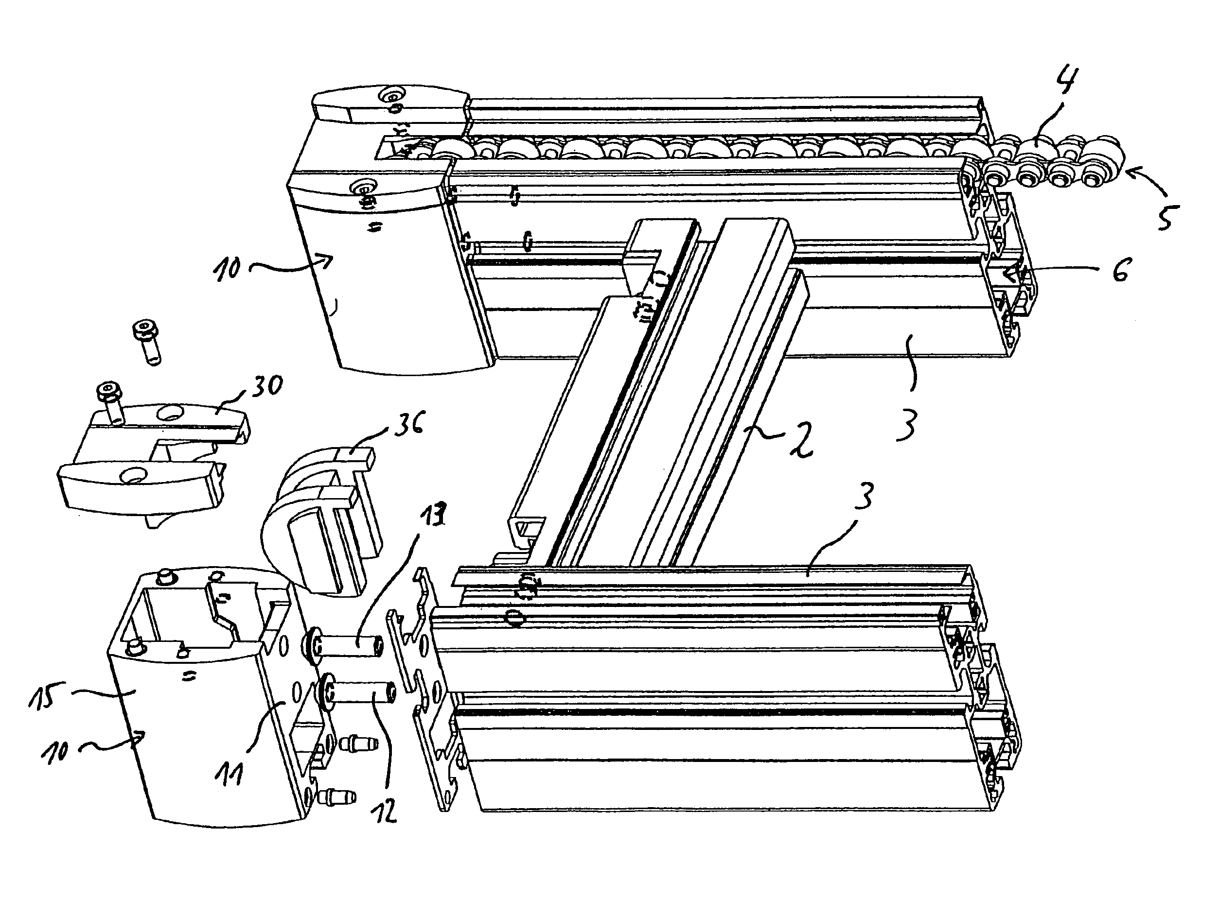
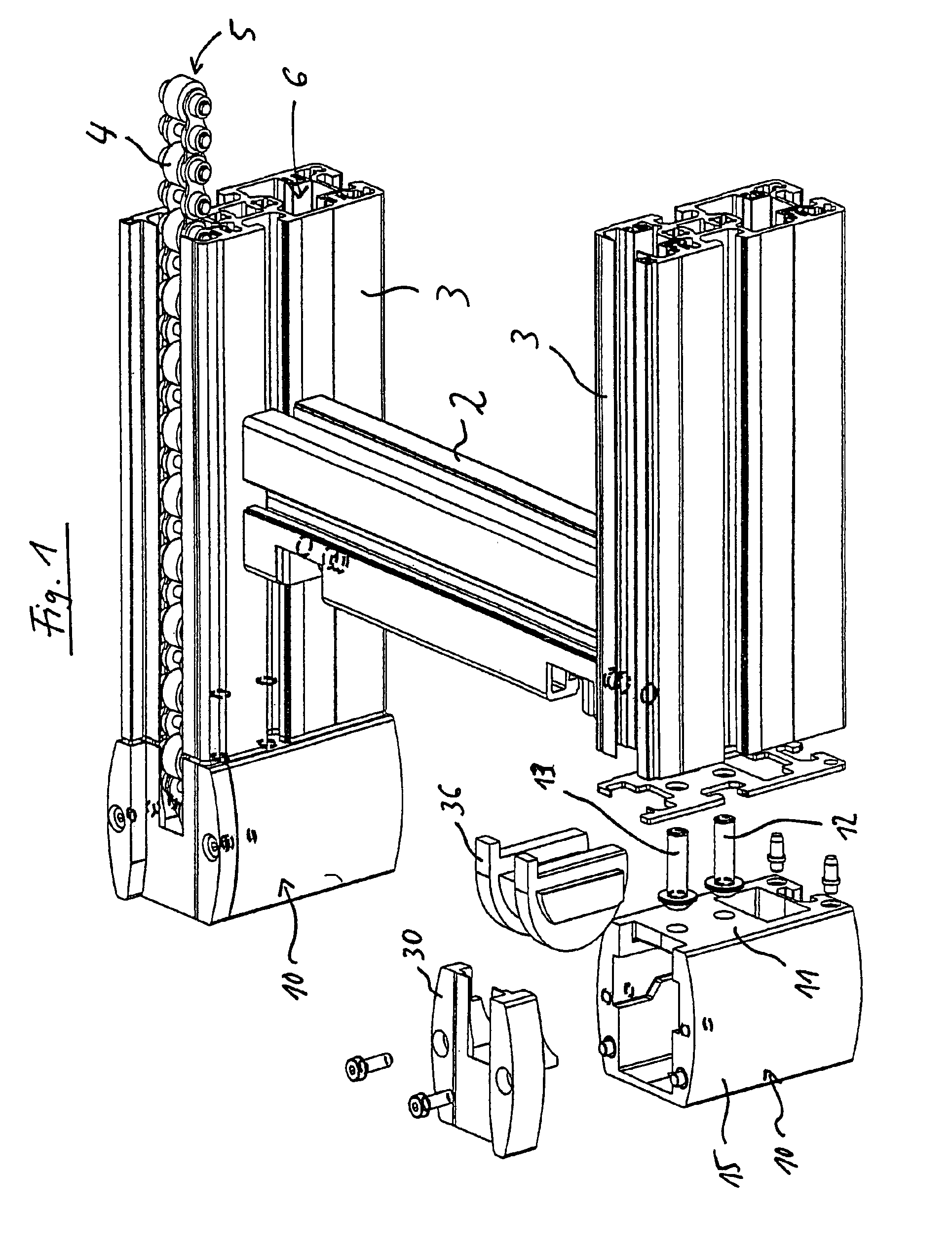
[0008]The turning device 10 shown in the figures is a component of a transfer system (not shown in greater detail), by means of which work piece carriers or the like can be conveyed between work stations, for example. The transfer system—only part of which is shown—comprises profiled line elements 3 situated parallel to each other and serving as transfer line, which said profiled line elements are interconnected by means of crossbars 2. A turning element 10 is capable of being mounted on each end face of a profiled line element 3, i.e., on a mounting surface 11, by means of screws 12, 13 with a stop plate as an intermediate layer. Positioning pins 14 under the screws 12, 13 serve to position the respective turning device 10 on the profiled line element 3. The turning device 10 serves to redirect an endless conveyance means, such as a chain carrier 4, from the transfer plane 5 into a return plane 6.

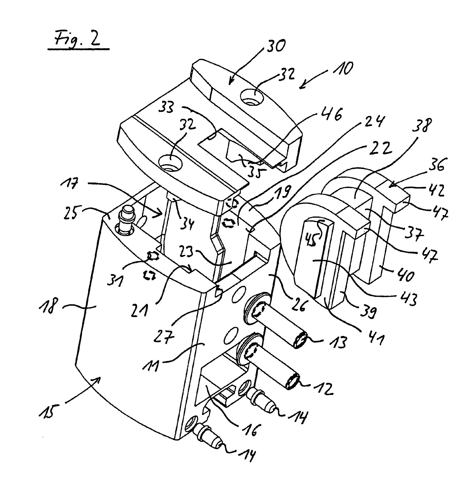
[0009]The turning device 10 comprises a metallic housing 15 that is produced preferabl...


PUM


Abstract

A turning device (10) for a conveyance device (4) on a transfer line includes a housing (15) closed by means of a cover (30). Recesses are formed in the housing (15), into which the guide bars (43) of a semicircular-shaped turning element (36) for the conveyance device (4) mesh with positive engagement. The design of the turning device (10) allows the conveyance device (4) to be replaced without requiring access through the side of the housing (15). Furthermore, the design of the turning device (10) is particularly compact.

Description

BACKGROUND OF THE INVENTION[0001]The invention concerns a turning device for a conveyance means on a transfer line. A known turning device of this type is a component of a transfer system that comprises, at the least, a drive head for the conveyance means, the transfer line formed out of profiled bars or the like, and the turning device. The turning device and the drive head are preferably located on the end surfaces and / or end faces of the profiled bars. The object of the turning device is to redirect the conveyance means overall from the incoming line to the outgoing line of the conveyance means by making one or multiple turns. With the known turning devices, the turning elements in the turning devices are realized as turn-around rollers, turn-around cylinders, toothed rollers or pinions. It is also essential that, in the case of the known turning devices, their housing is realized either as a basic, side-opening housing with a cover, or as a housing composed of two housing halves...

Claims


Application Information

Patent Timeline
Patent Type & Authority Patents(United States)
IPC IPC(8): B65G21/00B65G21/06B65G21/20
CPCB65G21/20B65G21/06B65G47/22
Inventor LEISNER, ERNSTSCHNEIDER, RALPHSCHOLPP, CLAUS
Owner ROBERT BOSCH GMBH
Why Eureka
Try Eureka