
Heater chip for an inkjet printhead

a printhead and heat sink technology, applied in printing and other directions, can solve the problem of no features on the backside of the chip, and achieve the effect of accurate and precise bond lines, increased chip surface area, and increased bond line height in the z direction

Inactive Publication Date: 2005-05-10
SLINGSHOT PRINTING LLC
View PDF22 Cites 9 Cited by
  • Summary
  • Abstract
  • Description
  • Claims
  • Application Information

AI Technical Summary

Benefits of technology

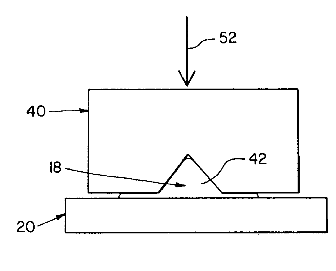
[0011]An advantage of the present invention is that the flow of the die attach adhesive can be precisely controlled.
[0012]Another advantage is that a very accurate and precise bond line is provided.
[0013]Yet another advantage is that a greater surface area of the chip is available for bonding over a given X distance on the chip.
[0014]A further advantage is that, for a set amount of adhesive, the height of the bond line in the Z direction and the width of the bond line in the X direction are greatly decreased.

Problems solved by technology

A problem is that there are no features on the backside of the chips to control the die attach adhesive flow during placement and cure.

Method used


Image

  • Heater chip for an inkjet printhead
  • Heater chip for an inkjet printhead
  • Heater chip for an inkjet printhead

Examples


Embodiment Construction

[0032]In FIG. 3 there is shown one embodiment of a silicon heater chip 26 of the present invention. Heater chip 26 includes a trench 28 encircling or surrounding a single ink via 30. The pattern of trench 28 could be created through micromachining techniques or by laser ablation with, for example, an yttrium aluminum garnet (YAG) laser.

[0033]In another embodiment (FIG. 4a), a trench 32 extends to the outside edges 34 of a chip 36 in each corner of chip 36. Thus, vents 38 are provided for the die attach adhesive to outgas during cure. The pattern of trench 32 can be created through micromachining techniques, by dicing with a dicing saw, or by laser ablation with a YAG laser. In yet another embodiment (FIG. 4b), additional vents 38 are provided by use of wet or dry micromachining or laser cutting techniques.

[0034]The results of cutting into a silicon chip via micromachining, dicing and YAG laser ablation are shown in FIGS. 5a, 5b and 5c, respectively. As can be seen in FIG. 5a, microm...


PUM


Abstract

An ink jet printhead assembly includes a heater chip having a backside with at least one cavity. A substrate is associated with the backside of the heater chip. Adhesive is at least partially disposed within the at least one cavity. The adhesive adheres the backside of the heater chip to the substrate.

Description

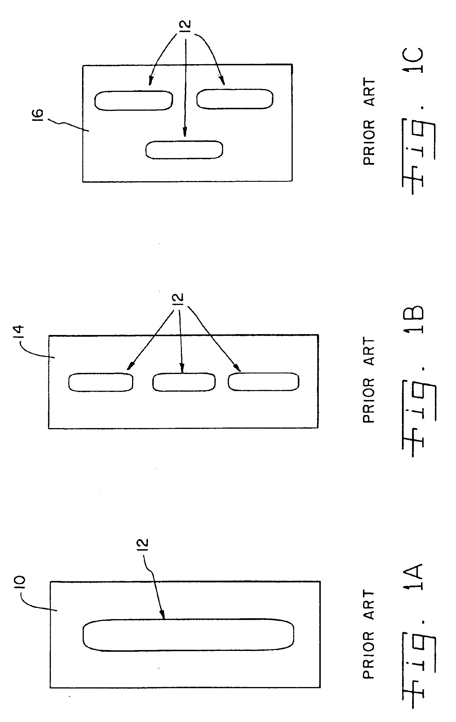
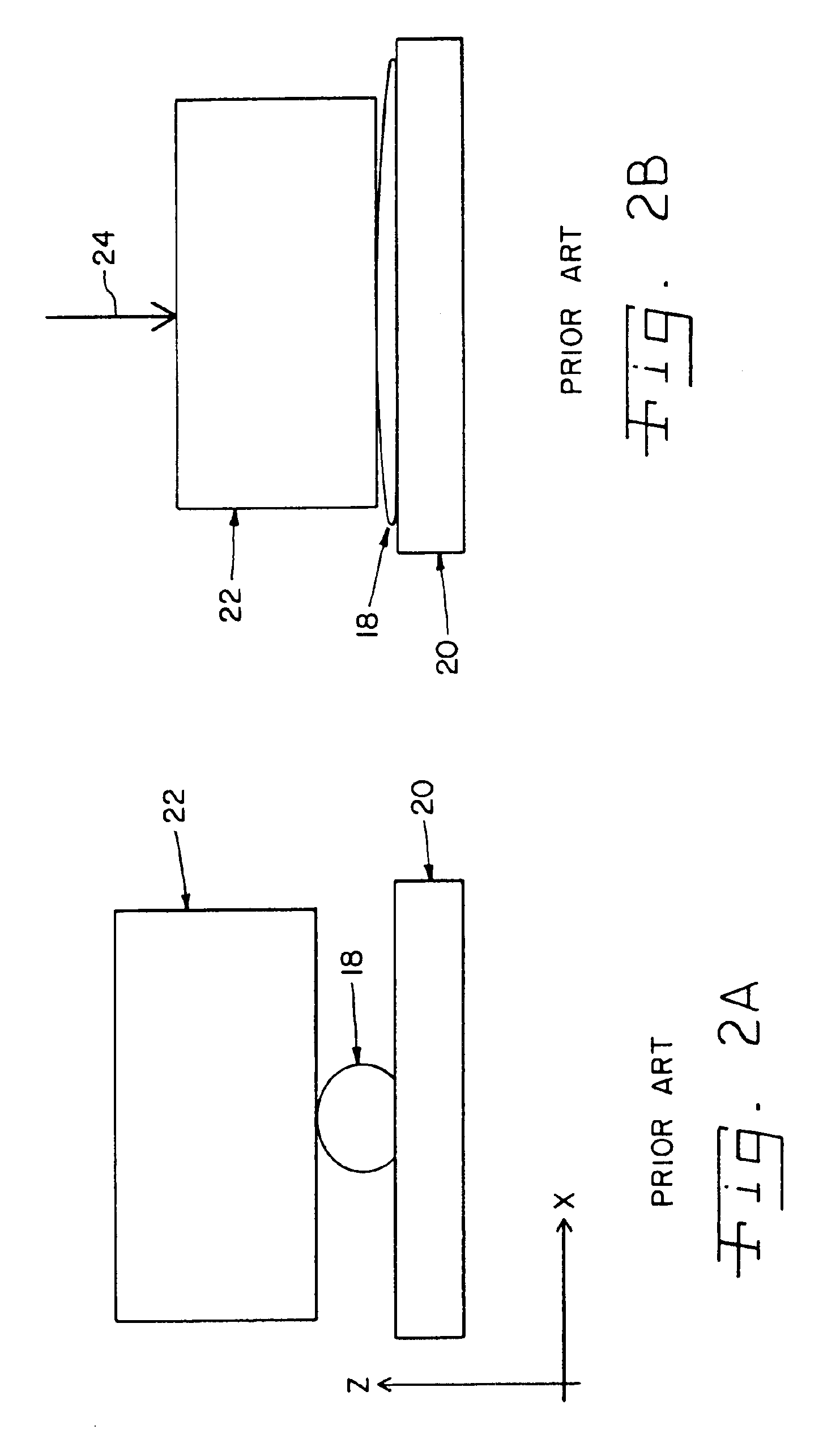
BACKGROUND OF THE INVENTION[0001]1. Field of the Invention[0002]The present invention relates to ink jet printheads, and, more particularly, to a heater chip for an ink jet printhead.[0003]2. Description of the Related Art[0004]A printhead in an ink jet printer includes a silicon heater chip 10 (FIG. 1a), also termed a “die,” containing a plurality of heating devices (not shown). Chip 10 has a single via 12. However, it is also possible for a chip to have multiple vias 12, such as chip 14 (FIG. 1b) or chip 16 (FIG. 1c). Other variations are of course possible. Each via 12 supplies ink from the backside of the heater chip to the front side of the chip, which is where the heating devices are located.[0005]It is known for a line of die attach adhesive to be dispensed onto a substrate in order to attach the heater chip to the substrate. Since adjacent ones of vias 12 may carry different colors of ink, the line of die attach adhesive must seal around and between each via 12 in order to p...

Claims


Application Information

Patent Timeline
Patent Type & Authority Patents(United States)
IPC IPC(8): B41J2/14B41J2/16
CPCB41J2/14024B41J2/1601B41J2/1623B41J2/1634B41J2/1629B41J2/1632B41J2/1628
Inventor SPIVEY, PAUL TIMOTHYSULLIVAN, CARL EDMONDUBELLACKER, KENT LEE
Owner SLINGSHOT PRINTING LLC
Learn More