
Electronically controlled multi-light flashlight

a multi-light, electric technology, applied in the field of flashlights, can solve the problems of limiting the flexibility of the flashlight to turn on the lights in different combinations, limiting the flexibility of the flashlight in brightness, beam length or power consumption, etc., and achieve the effect of convenient us

Inactive Publication Date: 2005-05-10
GOLD CORAL INT
View PDF6 Cites 58 Cited by
  • Summary
  • Abstract
  • Description
  • Claims
  • Application Information

AI Technical Summary

Benefits of technology

"The present invention provides a flashlight with multiple light sources that have different levels of power consumption, brightness, and beam lengths. The flashlight includes an integrated circuit or multi-state electronic device that controls the light sources using a pushbutton switch. The flashlight body is designed to direct the light from the multiple light sources, and each activation of the switch causes the integrated circuit to advance to a new state, resulting in different combinations of light sources being illuminated. This design allows users to control various aspects of the flashlight beam and power consumption with a simple switch, making the flashlight flexible and easy to use."

Problems solved by technology

For instance, the single-bulb flashlight generally has no flexibility in terms of brightness, beam length or power consumption.
Conventional multi-light flashlights, on the other hand, typically require multiple-contact switches, which often are more prone to becoming defective, and which limit the flashlight's flexibility to turn on the lights in different combinations.

Method used


Image

  • Electronically controlled multi-light flashlight
  • Electronically controlled multi-light flashlight
  • Electronically controlled multi-light flashlight

Examples


Embodiment Construction

)

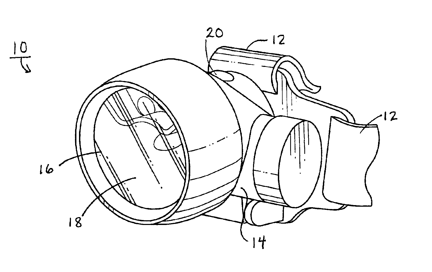
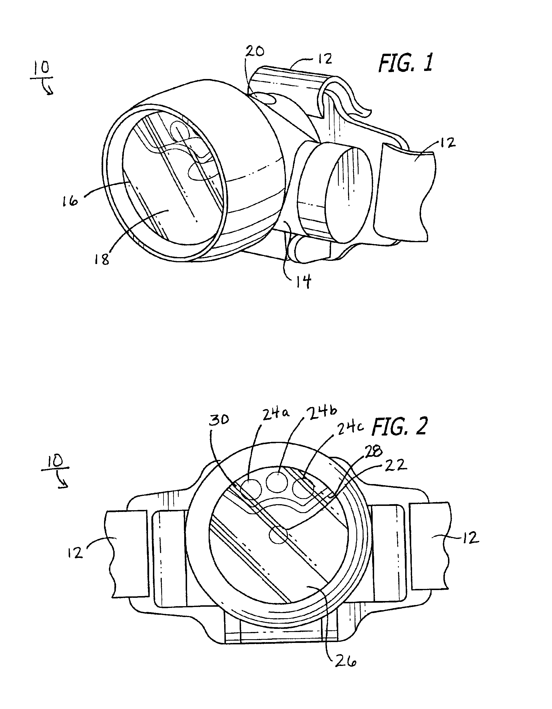
[0017]FIG. 1 illustrates a perspective view of a flashlight according to a representative embodiment of the present invention. As used herein, a flashlight is intended to mean any small (typically hand-sized) battery-powered device for producing a beam of light. In the embodiment shown in FIG. 1, the flashlight is configured as a headlight that is intended to be worn, using straps 12, on the user's head. However, a flashlight according to the present invention may be any other type of flashlight, such as a hand-held flashlight, a clip-on flashlight or a keychain flashlight.

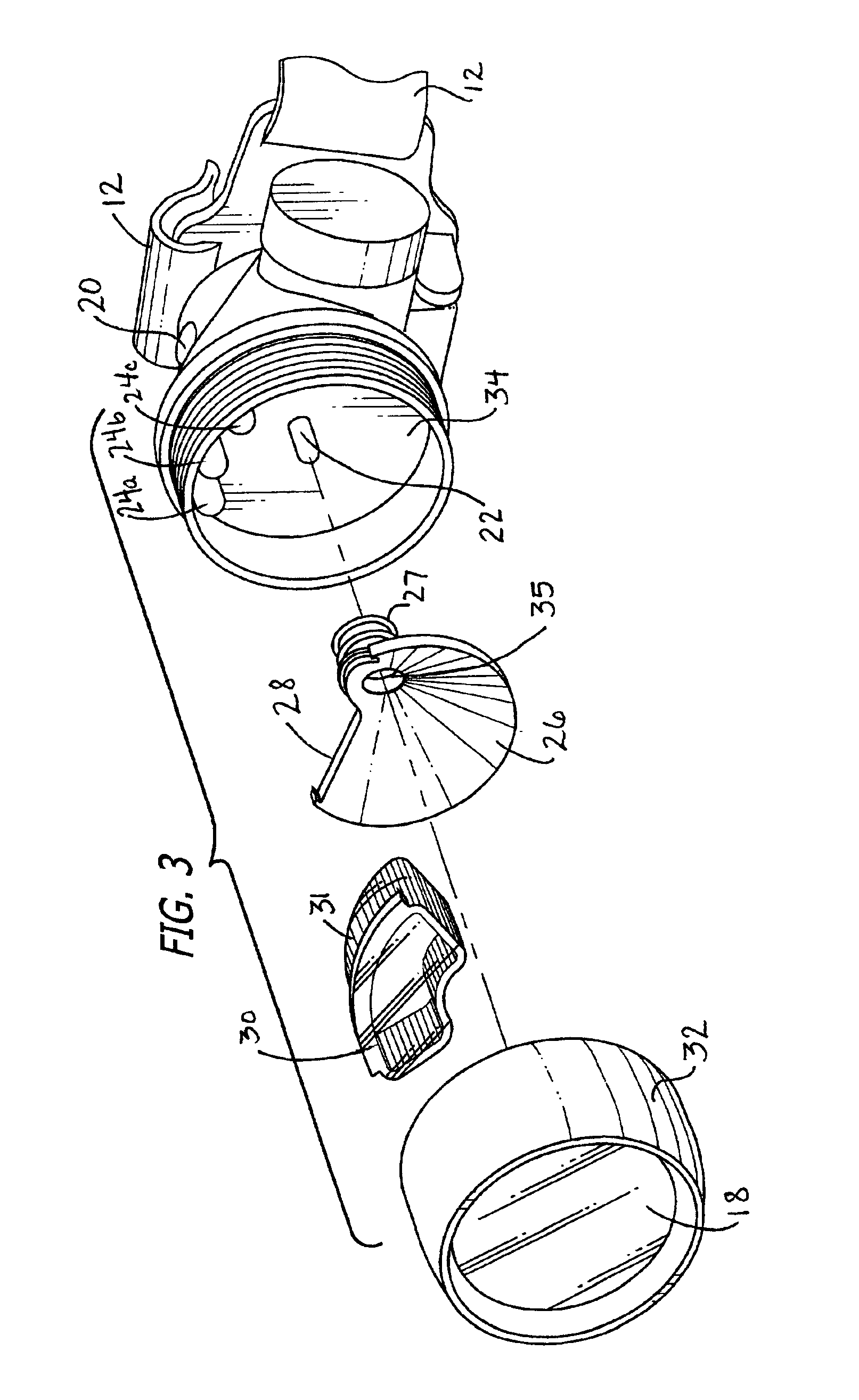
[0018]In the current embodiment, flashlight 10 includes a hand-sized flashlight body 14 that is opaque on all sides other than side 16. Covering side 16 is a clear plastic lens 18 which permits light to exit flashlight 10. In this way, flashlight 10 is configured to produce a beam of light in a single direction (i.e., from side 16).

[0019]Included on flashlight body 14 is a switch 20 for operating flashlight 10. I...


PUM


Abstract

Provided is a flashlight that includes a plurality of light sources for providing a beam of light. Preferably, the light sources have different levels of power consumption, different brightnesses and / or different beam lengths. More preferably, the plurality of light sources includes at least one light-emitting diode (LED) and at least one incandescent lamp. A housing directs the beam of light and an integrated circuit controls illumination of the plurality of light sources, with a switch providing an input signal to the integrated circuit. In the preferred embodiment of the invention, the switch is a pushbutton switch and the integrated circuit is a multi-state electronic device that changes state when the signal is input from the switch, with different states of the integrated circuit causing different combinations of the light sources to become illuminated.

Description

BACKGROUND OF THE INVENTION[0001]1. Field of the Invention[0002]The present invention concerns flashlights and is particularly directed to a flashlight having multiple light sources that are electronically controlled.[0003]2. Description of the Related Art[0004]Most conventional flashlights are simple mechanical devices that include a battery compartment, a single light bulb and a switch for opening and closing the electrical circuit between the battery and the light bulb. However, some conventional flashlights include multiple light bulbs and have a switch with additional contact positions to accommodate such multiple light bulbs.[0005]For instance, a flashlight with two bulbs might include a switch with three positions (e.g., an off position, a position in which only the first light bulb is illuminated and a position in which only the second light bulb is illuminated). In such a case, the middle position is usually the off position, sliding or rotating the switch to one side turns...

Claims


Application Information

Patent Timeline
Patent Type & Authority Patents(United States)
IPC IPC(8): F21V23/04F21L4/00F21V21/08F21V21/084F21L4/02H05B33/02H05B33/08H05B44/00
CPCF21L4/027F21V21/084H05B33/0803F21V23/0414Y10S362/80F21Y2101/02F21Y2115/10H05B45/30
Inventor SHIU, STEPHANIE WAI MAN
Owner GOLD CORAL INT
Learn More