Battery apparatus for controlling plural batteries and control method of plural batteries

a battery and control device technology, applied in the field of battery devices, can solve the problems of high cost of control devices, reliability problems, and battery apparatus cost reduction, and achieve the effects of reducing the cost of battery cells or capacitor cells themselves, and reducing the cost of battery apparatus

Inactive Publication Date: 2005-05-10
HITACHI AUTOMOTIVE SYST LTD
View PDF5 Cites 91 Cited by
  • Summary
  • Abstract
  • Description
  • Claims
  • Application Information

AI Technical Summary

Benefits of technology

[0007]Problems to be remedied by the present invention are following three. First, it is a cost problem. The secondary battery and the ultra capacitor are expected to be used for a battery apparatus for the electric car or the hybrid electric car, but it is demanded that their costs are reduced for mass production. For the cost reduction of the battery apparatus, it is necessary to reduce the cost of the battery cell or the capacitor cell itself and also to reduce the costs of the plural low order control devices. To achieve it, it is effective to have the low order control devices as ICs (integrated circuits).

Problems solved by technology

First, it is a cost problem.
Thus, a total of 20 isolating units are necessary, and there is a disadvantage that the control devices cost high.
Second, there is a problem of reliability.
There is a possibility that an external interference enters the instruction signal due to noise produced by an inverter device or the like which is connected as a load on the battery apparatus.
Therefore, there is a problem that the reliability of the signal transmission is decreased when instructions are given from the high order control device to the low order control devices because of the external interference.
Third, there is a problem of accuracy of detecting a voltage.
But, it is said that even the lithium-ion battery has an allowable error of ±50 mV or less in voltage equalization for the capacity adjustment.

Method used


Image

  • Battery apparatus for controlling plural batteries and control method of plural batteries
  • Battery apparatus for controlling plural batteries and control method of plural batteries
  • Battery apparatus for controlling plural batteries and control method of plural batteries

Examples


Embodiment Construction

[0041]The battery apparatus and its control method according to one embodiment of the invention will be described with reference to FIG. 1 to FIG. 10.

[0042]First, a general structure of the battery apparatus according to this embodiment will be described with reference to FIG. 1.

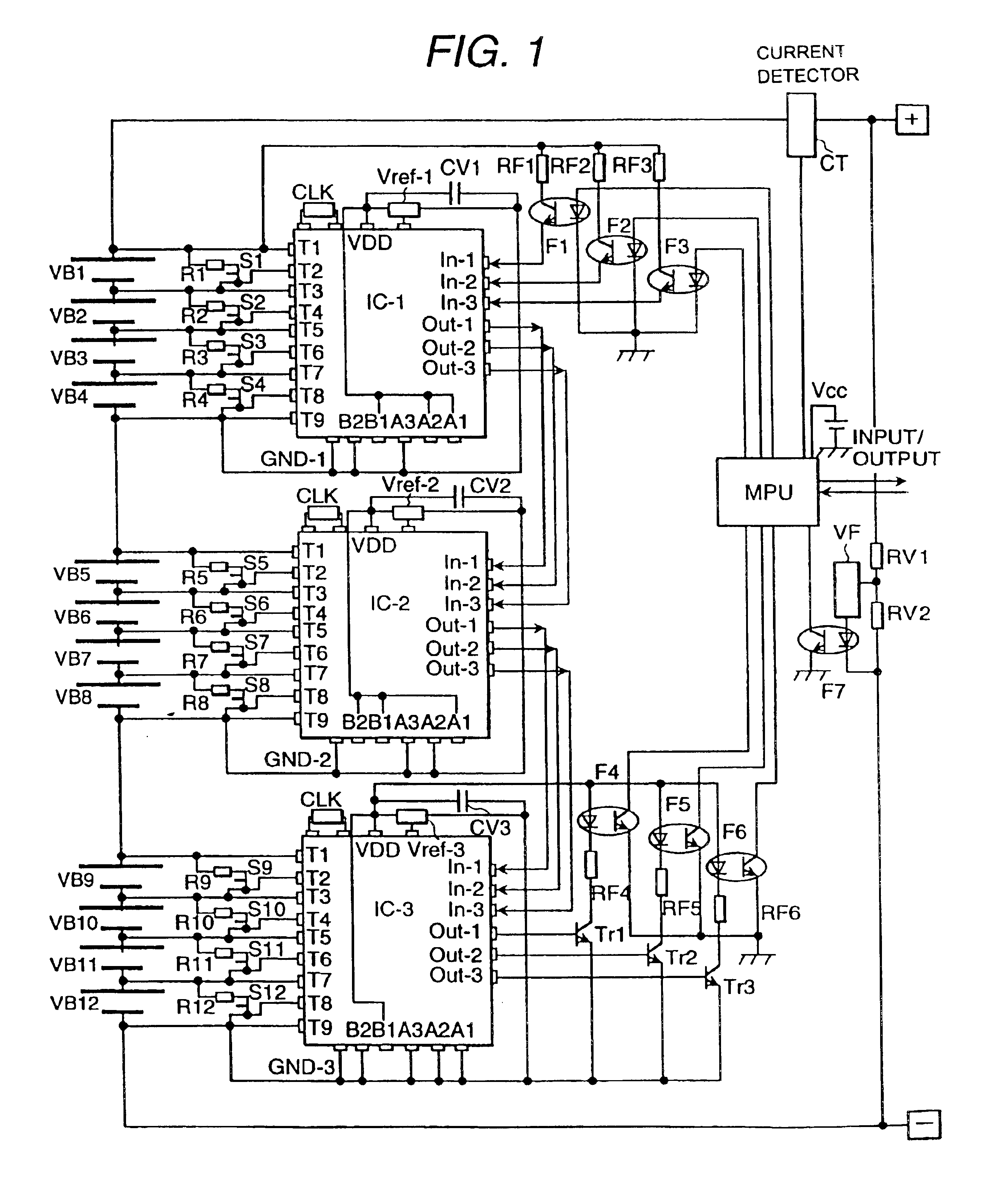
[0043]FIG. 1 is a circuit diagram showing the general structure of the battery apparatus according to one embodiment of the invention.

[0044]Electric cells VB1, VB2, . . . , VB12 which are secondary batteries are divided into battery modules each of which has four battery cells connected in series. A secondary battery apparatus used for an electric car or a hybrid electric car may be provided with tens to twenties of battery modules. But, this embodiment always has the same structure even when many modules are connected in series, so that the example of FIG. 1 shows a structure example having three battery modules connected in series.

[0045]In the shown example, a first battery module in the highest potential ...


PUM

PropertyMeasurementUnit
voltageaaaaaaaaaa
voltageaaaaaaaaaa
voltageaaaaaaaaaa

Abstract

Lower order control devices control plural battery cells configuring plural battery modules. An input terminal of the low order control device in the highest potential, an output terminal of the low order control device in the lowest potential, and a high order control device are connected by isolating units, photocouplers. Diodes which prevent a discharge current of the battery cells in the battery modules are disposed between the output terminal of the low order control device and the battery cells in the battery module on the low potential side. Terminals related to input/output of a signal are electrically connected without isolating among the plural low order control devices.

Description

CROSS REFERENCE TO RELATED APPLICATIONS[0001]The present application is a continuation application of U.S. patent application Ser. No. 10 / 079,423, filed on Feb. 22, 2002, now U.S. Pat. No. 6,762,588 the disclosure of which is herewith incorporated by reference in its entirety.BACKGROUND OF THE INVENTION[0002]The present invention relates to a battery apparatus for controlling plural high energy battery cells connected in series and its control method, and more particularly to a battery apparatus which is suitable for a low order control device which controls a battery module having plural battery cells connected in series and a high order control device for giving instructions to plural low order control devices.[0003]For example, Japanese Patent Laid-Open Publication No. 10-322925 describes a conventional battery apparatus which is comprised of plural battery cells connected in series as a battery module, plural battery modules being connected in series, and a low order control dev...

Claims


Application Information

Patent Timeline
Patent Type & Authority Patents(United States)
IPC IPC(8): H02J7/00H01M50/529H02J7/02B60L11/18H01M10/44H01M50/569
CPCH02J7/0026H02J7/0022H02J7/0021H02J7/0019H02J7/0016H02J7/0013H01M10/482H01M10/425B60L11/1879B60L11/1864B60L11/1855B60L11/185Y02E60/12Y02T90/121Y02T90/14Y02T10/7088Y02T10/7061Y02T10/7055Y02T10/7011Y02T10/7005H01M2220/20H01M2010/4278H01M2010/4271H01M10/052G01R31/3658Y02T90/128Y02T10/7072B60L53/11B60L58/19B60L58/21B60L50/64G01R31/396Y02E60/10Y02T10/70H02J7/00302H02J7/00306H02J7/0048H01M50/569Y02T90/12
Inventor MIYAZAKI, HIDEKIEMORI, AKIHIKOKUDO, AKIHIKOKAI, TSUYOSHI
Owner HITACHI AUTOMOTIVE SYST LTD
Why Eureka
Try Eureka