
Backlight assembly of liquid crystal display device

Inactive Publication Date: 2005-05-10
LG DISPLAY CO LTD
View PDF10 Cites 29 Cited by
  • Summary
  • Abstract
  • Description
  • Claims
  • Application Information

AI Technical Summary

Benefits of technology

[0017]An advantage of the present invention is to provide a backlight assembly of an LCD device in a liquid crystal panel, in which it is possible to prevent light from leaking, the LCD device having a simplified manufacturing process.
[0018]Additional advantages and features of the invention will be set forth in part in the description which follows and in part will become apparent to those having ordinary skill in the art upon examination of the following or may be learned from practice of the invention. These and other advantages of the invention may be realized and attained by the structure particularly pointed out in the written description and claims hereof as well as the appended drawings.
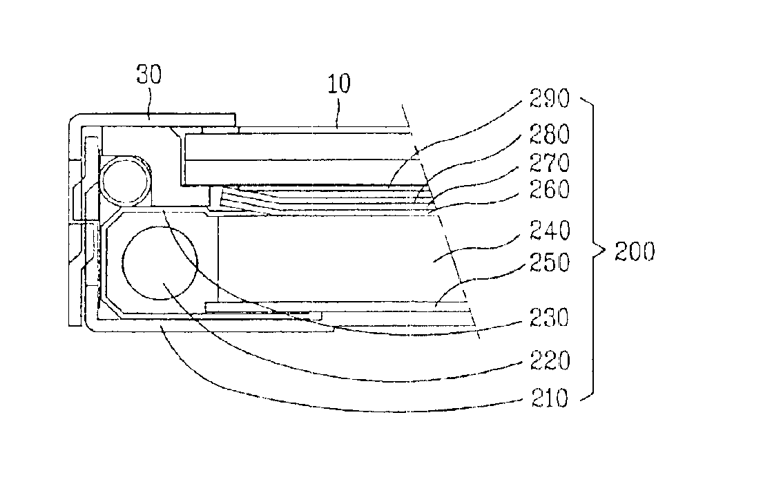
[0019]To achieve these and other advantages and in accordance with the purpose of the invention, as embodied and broadly described herein, a backlight assembly of a liquid crystal display (LCD) device according to the present invention, for emitting light for an entire surface of a liquid crystal panel, includes a rectangular mold frame, a lamp for emitting light mounted at one side of the mold frame, a metal reflecting plate surrounding one part of the lamp mounted at the side of the mold frame having the lamp, a light-guiding plate mounted in parallel with the lamp at the mold frame, a reflecting sheet positioned under the light-guiding plate, a plurality of diffusion and prism sheets positioned on the light-guiding plate, wherein each edge of the diffusion and prism sheets is extended to upper surfaces of the metal reflecting plate and the mold frame.

Problems solved by technology

When external force impacts on the LCD device, the sheets are moved to one side, so that the light leakage increases to further deteriorate the image display.
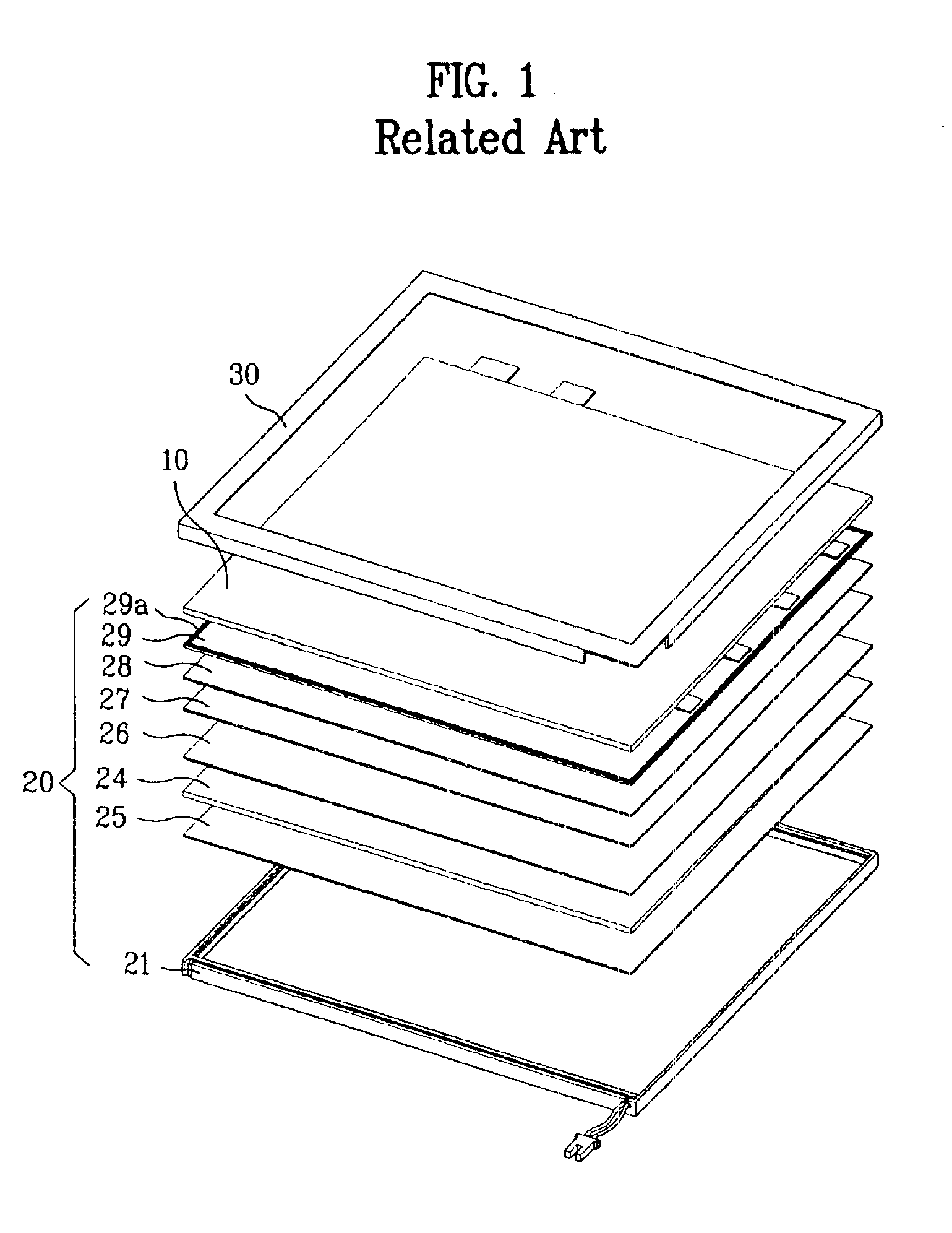
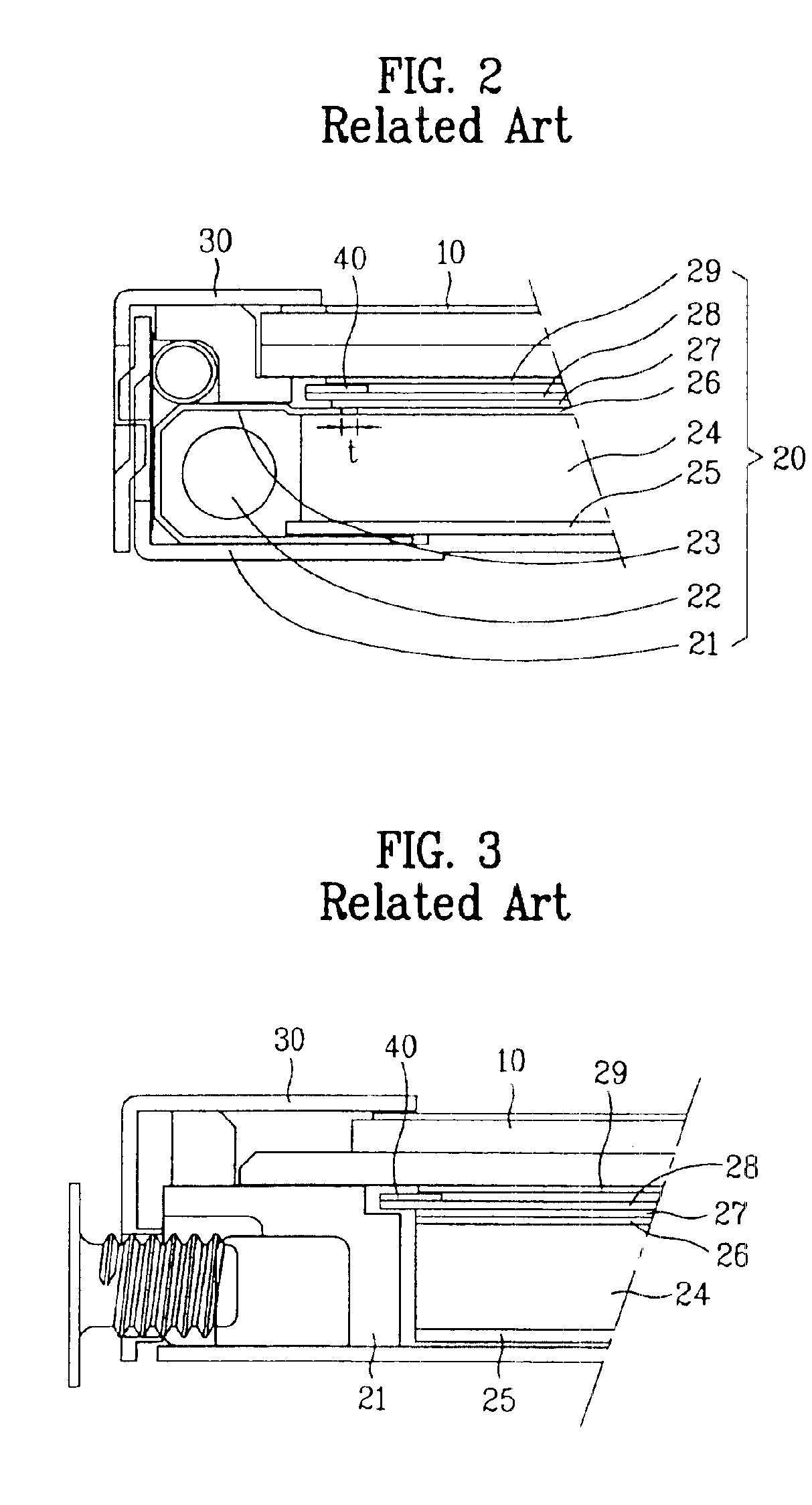
First, if the black matrix 29a is formed on the upper diffusion sheet 29 to prevent light from leaking in the gap ‘t’, manufacturing process steps are complicated.
Also, if the pad 40 is interposed between the upper diffusion sheet and the upper prism sheet to prevent light from leaking in the gap ‘t’, the thickness of the LCD device is increased, which makes the device less desirable for use in a notebook computer or other portable device.

Method used


Image

  • Backlight assembly of liquid crystal display device
  • Backlight assembly of liquid crystal display device
  • Backlight assembly of liquid crystal display device

Examples


Embodiment Construction

[0028]Reference will now be made in detail to the illustrated embodiments of the present invention, examples of which are illustrated in the accompanying drawings. Wherever possible, the same reference numbers will be used throughout the drawings to refer to the same or like parts.

[0029]FIG. 4 and FIG. 5 are sectional views illustrating lower and lateral parts in an LCD module of a portable computer having a backlight assembly according to the present invention.

[0030]Referring to FIG. 4 and FIG. 5, the LCD module is provided with a liquid crystal panel 10, a backlight assembly 200 and a metal chassis 30.

[0031]The liquid crystal panel 10 is provided with two polarizers and a liquid crystal injected between the two polarizers for outputting an image. Then, the backlight assembly is mounted at the rear of the liquid crystal panel 10 for emitting light to an entire surface of the liquid crystal panel 10. The rectangular metal chassis 30 fixes and supports each corner of the liquid cryst...


PUM


Abstract

A backlight assembly of a liquid crystal display (LCD) device is disclosed, in which each edge of the diffusion and prism sheets is extended to upper surfaces of the metal reflecting plate and the mold frame, so that it is possible to prevent light emitted from a lamp from leaking into a liquid crystal panel without passing through one of the diffusion and prism sheet.

Description

[0001]This application claims the benefit of Korean Patent Application No. 2001-41346, filed on Jul. 10, 2001, which is hereby incorporated by reference for all purposes as if fully set forth herein.BACKGROUND OF THE INVENTION[0002]1. Field of the Invention[0003]The present invention relates to a backlight assembly of a flat type liquid crystal display (LCD) device, and more particularly, to a backlight assembly of an LCD device for preventing light emitted from a lamp from leaking into a liquid crystal panel without passing through a diffusion or prism sheet of the backlight assembly.[0004]2. Discussion of the Related Art[0005]In general, a liquid crystal display (LCD) device, one type of flat display, provides excellent visual perception as compared to a cathode-ray tube (CRT), consumes much less power than a CRT of the same size, and produces significantly less heat. Because of these features, in addition to a plasma display panel (PDP) and a field emission display (FED), the LCD...

Claims


Application Information

Patent Timeline
IPC IPC(8): F21V8/00G02F1/1335G02F1/13F21Y103/00G02F1/13357
CPCG02B6/0086G02F1/133615G02F1/133308G02F1/1335
Inventor JANG, MYONG GIWON, SE CHANGYOU, DONG JAE
Owner LG DISPLAY CO LTD
Learn More