Image forming apparatus and method of controlling the apparatus

a technology of image forming apparatus and control apparatus, which is applied in the direction of electrical apparatus, pictoral communication, etc., can solve the problem of requiring about five minutes of cold cathode ray tube, and achieve the effect of quick reading and preventing the thermal effect of the surrounding parts of the exposure lamp

Inactive Publication Date: 2005-05-10
KK TOSHIBA +1
View PDF1 Cites 8 Cited by
  • Summary
  • Abstract
  • Description
  • Claims
  • Application Information

AI Technical Summary

Benefits of technology

[0005]An object of the invention is to provide an image forming apparatus and a method of controlling the apparatus, wherein thermal effects on the surrounding parts of an exposure lamp can be prevented and a quick reading can be performed without having a user felt dazzled, and moreover, the exposure lamp can be also used for the purpose of illuminating a control panel.

Problems solved by technology

However, the cold-cathode ray tube requires about five minutes from the time it is lit until the quantity of light is sufficiently stabilized.

Method used


Image

  • Image forming apparatus and method of controlling the apparatus
  • Image forming apparatus and method of controlling the apparatus
  • Image forming apparatus and method of controlling the apparatus

Examples


first embodiment

[0025][1] Now, the invention will be described with reference to the drawings.

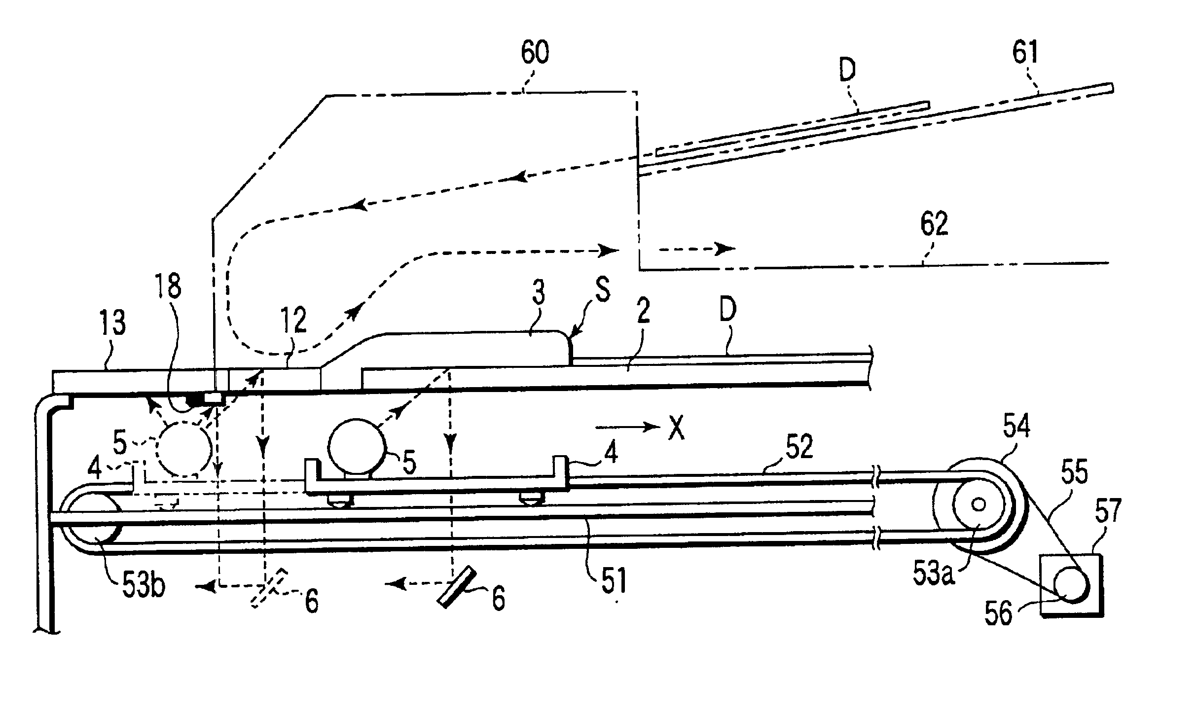
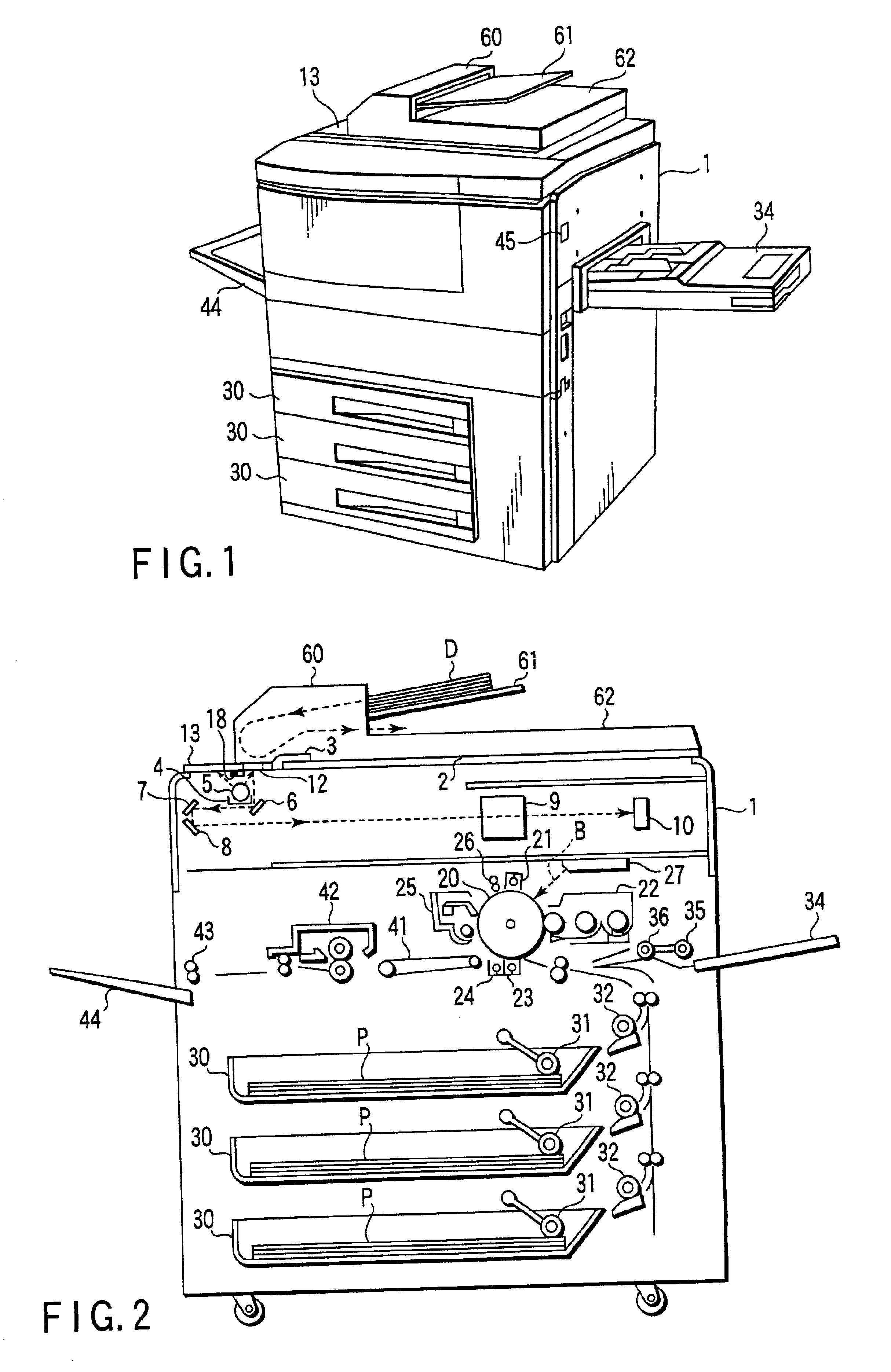
[0026]As shown in FIG. 1 and FIG. 2, a transparent document setting plate (glass plate) 2 for mounting an document is provided on an upper surface portion of a main body 1, and a cover 3 is provided on the document setting plate 2 in such a manner as to flexibly open and close.

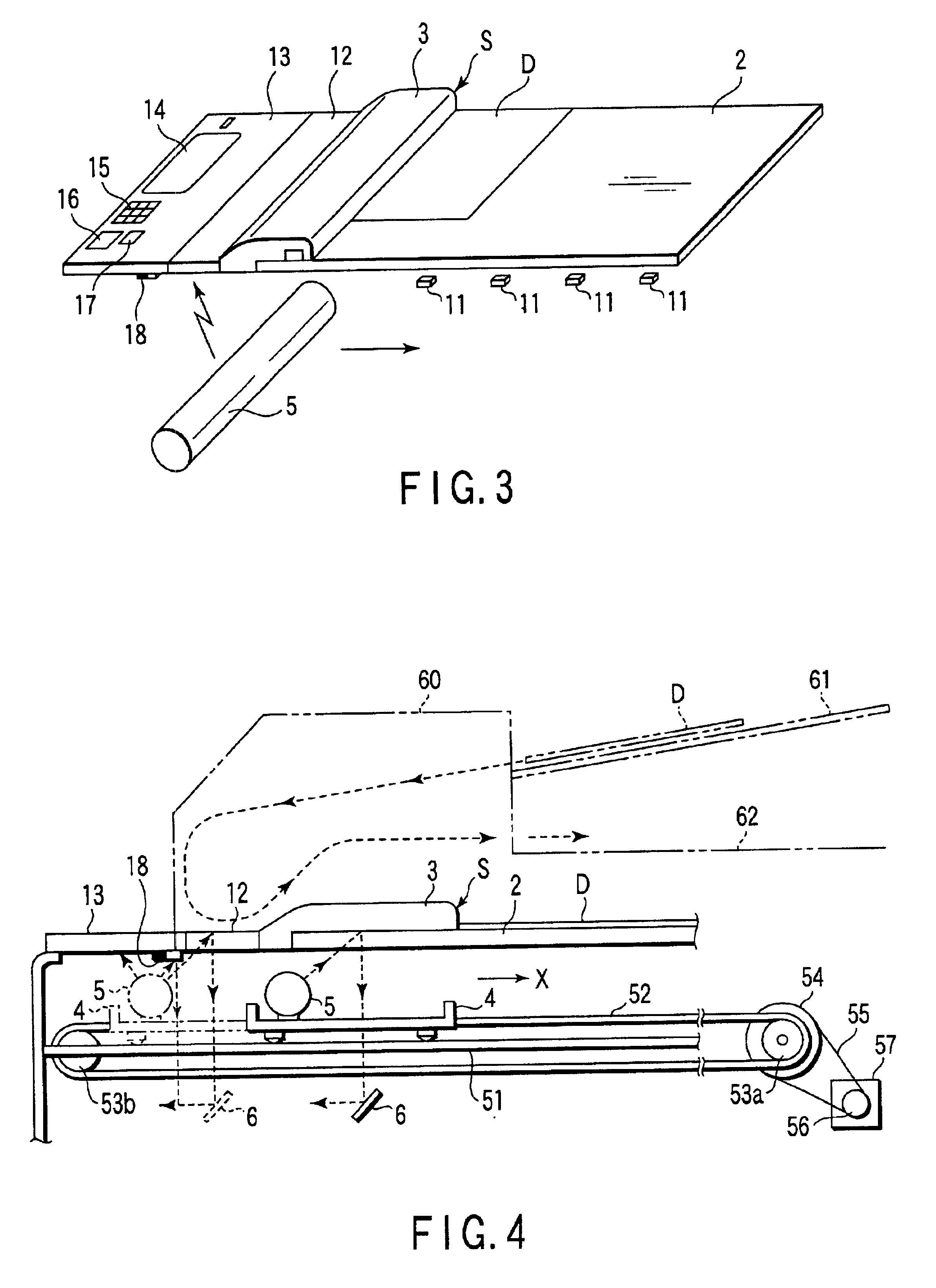
[0027]As shown in FIG. 3 and FIG. 4, one side portion of the document setting plate 2 is provided with an indicate portion 3. A stepped portion between this indicator portion 3 and the document setting plate 2 is made as a reference position S for setting the document. An document D is set by fitting to this reference position S. That is, with the reference position S as a boundary, the indicator portion 3 side (shown in the left side) is a non-document mounting area and the remaining side (shown in the right side) is an document mounting area.

[0028]The lower surface side of the document setting plate 2 is provided with a plurality o...

second embodiment

[0076][2] the invention will be described below with reference to the drawings.

[0077]As shown in FIG. 9, on the upper surface portion of a main body 1, an operation condition setting control panel 13 is provided at a position on which an automatic document feeder 60 does not overlay and also at a position where the light of an exposure lamp 5 does not reach.

[0078]In this case, as shown in FIG. 10, when the exposure lamp 5 exists at first and second standby positions, the light of the exposure lamp 5 is irradiated at a light receiving portion 65 via a reflection mirror 64. Also, as shown in FIG. 11, a back light panel 66 is provided by opposing to the lower surface of the control panel 13. The light which the light receiving portion 65 received is guided to the back light panel 66 by an optical fiber 67. The back light panel 66 irradiates the light to be guided by the optical fiber 67 toward the lower surface of the control panel 13.

[0079]The other constitution is the same as that of...


PUM


Abstract

A cold-cathode ray tube is adopted as an exposure lamp and the exposure lamp is always lit. When the exposure lamp exists at a standby position, a light of the exposure lamp is irradiated at a lower surface side of a control panel. By this irradiation, the liquid crystal display section of the control panel is irradiated in a state of looking bright and clear.

Description

BACKGROUND OF THE INVENTION[0001]An image forming apparatus such as a copying machine optically reads an image of an document set on an document setting plate via a transparent document setting plate by moving and lighting an exposure lamp along the document setting plate. The read image is printed on a copy paper, which is an image forming medium.[0002]As an example of the exposure lamp, there are a halogen lamp and a cold-cathode ray tube. While the halogen lamp is high in a calorific value, the cold-cathode ray tube is low in the calorific value. When this cold-cathode ray tube is used, thermal effects (deformation, fracture and the like) on the surrounding parts can be prevented.[0003]However, the cold-cathode ray tube requires about five minutes from the time it is lit until the quantity of light is sufficiently stabilized. For this reason, when the cold-cathode ray tube is adopted as an exposure lamp, in order to prevent a delay in the start of reading, the cold-cathode ray tu...

Claims


Application Information

Patent Timeline
Patent Type & Authority Patents(United States)
IPC IPC(8): H04N1/10H04N1/40H04N1/191H04N1/193
CPCH04N1/00411H04N1/0287H04N1/40056H04N1/1013H04N2201/044H04N1/193
Inventor KONNO, MICHIAKI
Owner KK TOSHIBA
Why Eureka
Try Eureka