
Targeted Copy of Data Relocation

Active Publication Date: 2015-05-28
SANDISK TECH LLC
View PDF10 Cites 26 Cited by
  • Summary
  • Abstract
  • Description
  • Claims
  • Application Information

AI Technical Summary

Benefits of technology

The invention relates to a memory system that can detect and repair damaged data in a nonvolatile memory. By using a binary cache and an MLC main memory, the system can identify and copy damaged data along a specific line in the MLC memory to the faster binary cache. This improves the speed of reading frequently accessed data. The technical effect of this invention is to increase the resilience of nonvolatile memory arrays and improve their performance.

Problems solved by technology

Thus, data is relocated before it becomes uncorrectable.

Method used


Image

  • Targeted Copy of Data Relocation
  • Targeted Copy of Data Relocation
  • Targeted Copy of Data Relocation

Examples


Embodiment Construction

Memory System

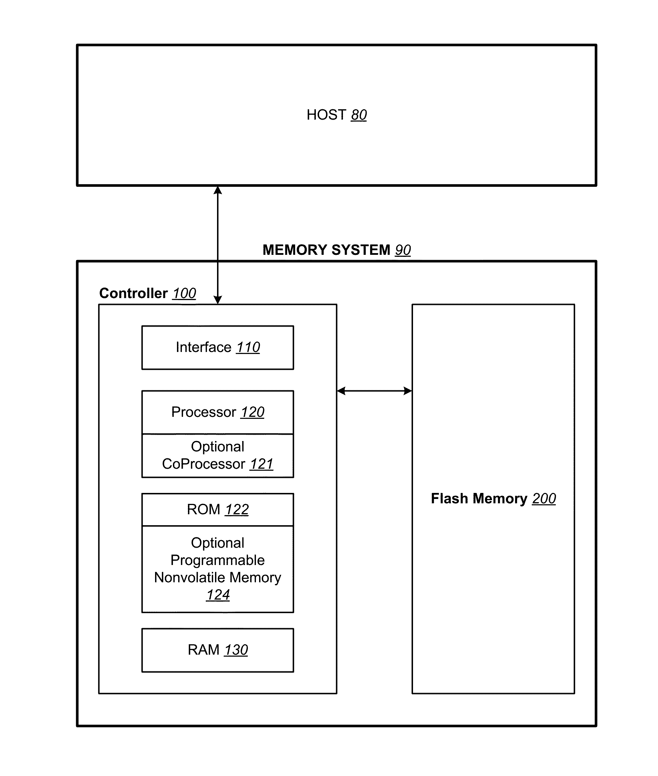
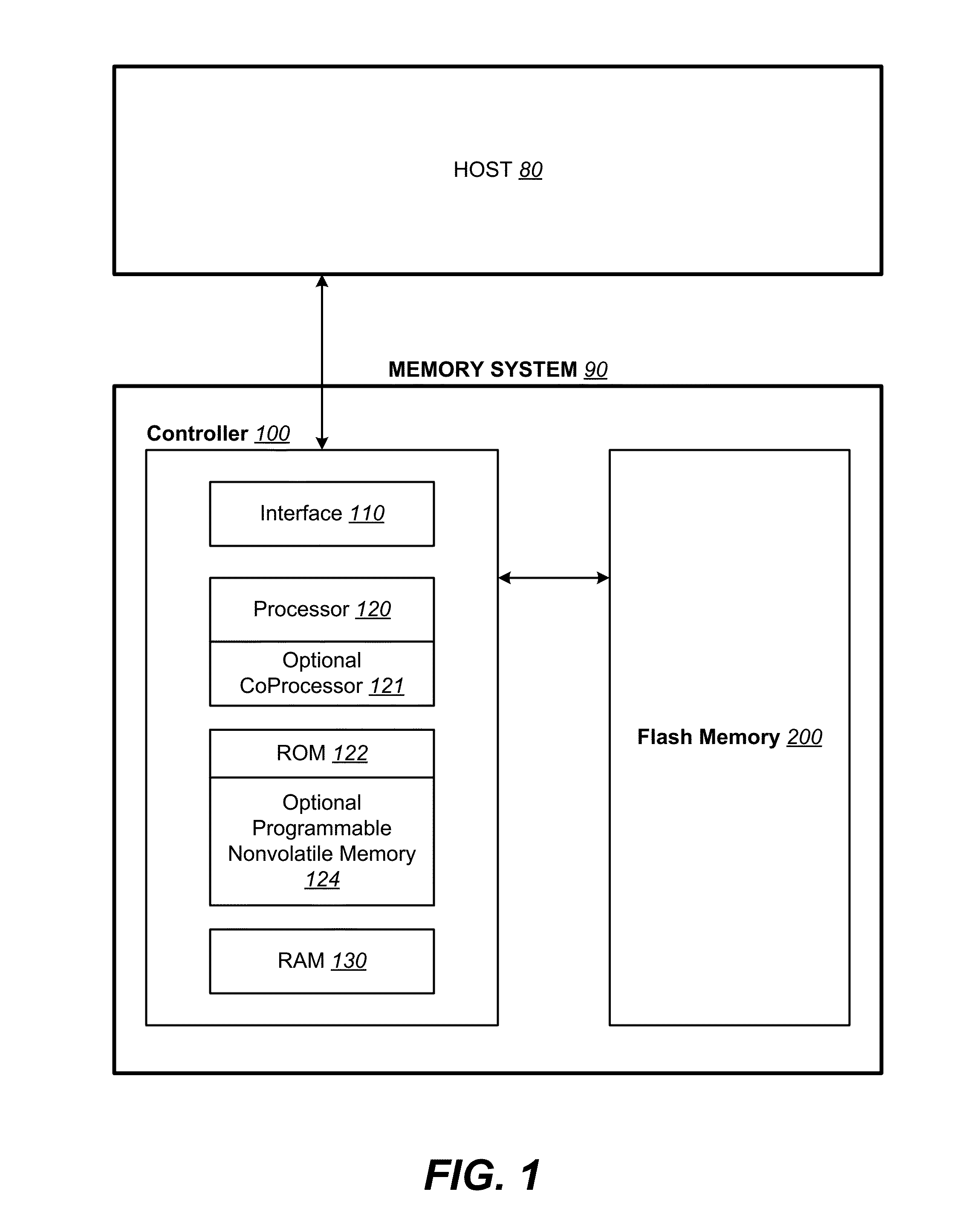
[0030]FIG. 1 illustrates schematically the main hardware components of a memory system suitable for implementing the present invention. The memory system 90 typically operates with a host80 through a host interface. The memory system is typically in the form of a memory card or an embedded memory system. The memory system 90 includes a memory 102 whose operations are controlled by a controller 100. The memory 102 comprises one or more array of non-volatile memory cells distributed over one or more integrated circuit chip. The controller 100 may include interface circuits, a processor, ROM (read-only-memory), RAM (random access memory), programmable nonvolatile memory, and additional components. The controller is typically formed as an ASIC (application specific integrated circuit) and the components included in such an ASIC generally depend on the particular application.

Physical Memory Structure

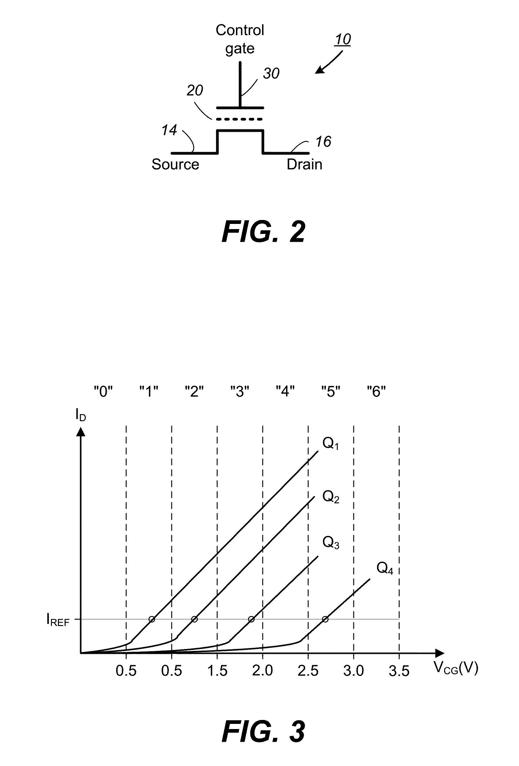
[0031]FIG. 2 illustrates schematically a non-volatile memory cell. The memor...


PUM


Abstract

In a nonvolatile memory array that has a binary cache formed of SLC blocks and a main memory formed of MLC blocks, corrupted data along an MLC word line is corrected and relocated, along with any other data along the MLC word line, to binary cache, before it becomes uncorrectable. Subsequent reads of the relocated data directed to binary cache.

Description

BACKGROUND[0001]This application relates to the operation of re-programmable non-volatile memory systems such as semiconductor flash memory that can store one or more bits per cell by writing multiple states, and more specifically, to operating such memories in an efficient manner.[0002]Solid-state memory capable of nonvolatile storage of charge, particularly in the form of EEPROM and flash EEPROM packaged as a small form factor card, has become the storage of choice in a variety of mobile and handheld devices, notably information appliances and consumer electronics products. Unlike RAM (random access memory) that is also solid-state memory, flash memory is non-volatile, and retains its stored data even after power is turned off. Also, unlike ROM (read only memory), flash memory is rewritable similar to a disk storage device. Flash memory is increasingly being used in mass storage applications.[0003]Flash EEPROM is similar to EEPROM (electrically erasable and programmable read-only ...

Claims


Application Information

Patent Timeline
IPC IPC(8): G06F3/06G11C16/34G11C11/56
CPCG06F3/0619G11C11/5628G06F3/0679G06F3/065G06F3/0652G11C16/3431G11C16/10G11C16/3495G11C2211/5641G11C16/0483
Inventor NG, YEW YINKOCHAR, MRINALYANG, NILESDUTTA, DEEPANSHU
Owner SANDISK TECH LLC
Learn More