System and method for improved motor controller

a motor controller and system technology, applied in the field of motor controllers, can solve the problems of increasing inventory and thus manufacturing costs, increasing costs, and increasing costs, and achieve the effect of reducing inventory requirements and reducing manufacturing costs

Inactive Publication Date: 2005-05-10
SIEMENS ENERGY & AUTOMATION INC
View PDF15 Cites 30 Cited by
  • Summary
  • Abstract
  • Description
  • Claims
  • Application Information

AI Technical Summary

Benefits of technology

The invention provides better ways for making motors than what was previously available. This makes them cheaper and easier to make.

Problems solved by technology

The technical problem addressed in this patent text is the high cost and complexity of designing and manufacturing solid state starters/controllers for controlling power application to AC induction motors. Different configurations require different parts, leading to higher inventory requirements and manufacturing costs. The invention aims to simplify the design and reduce the complexity of the controller.

Method used


Image

  • System and method for improved motor controller
  • System and method for improved motor controller
  • System and method for improved motor controller

Examples


Embodiment Construction

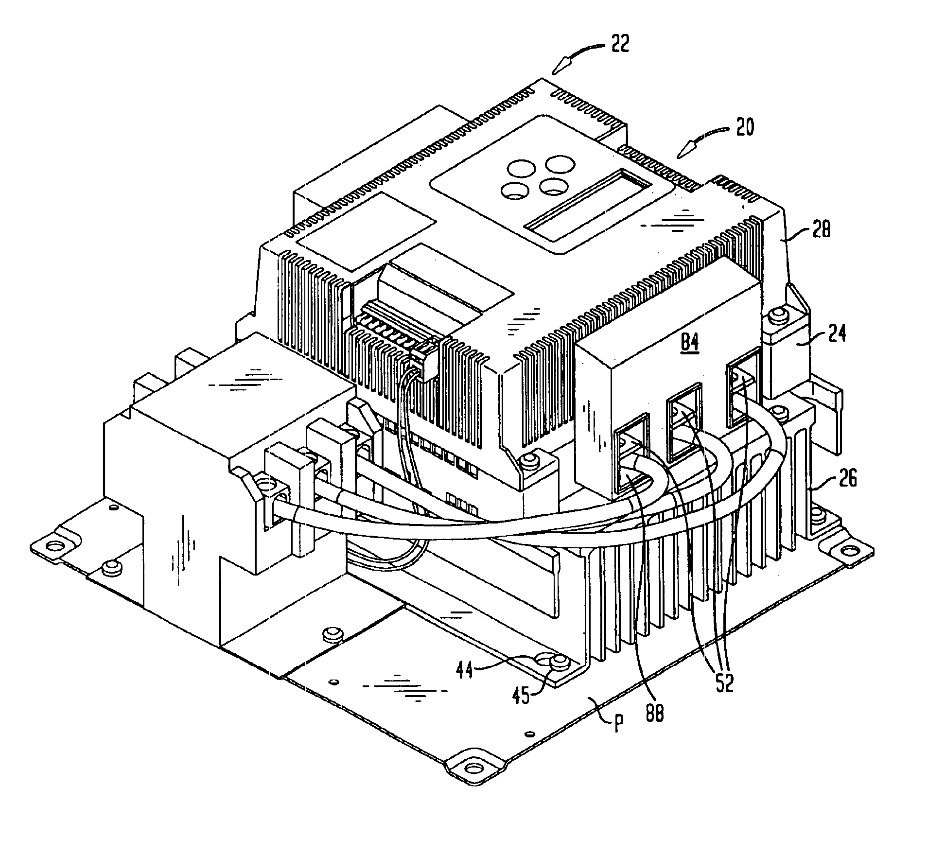
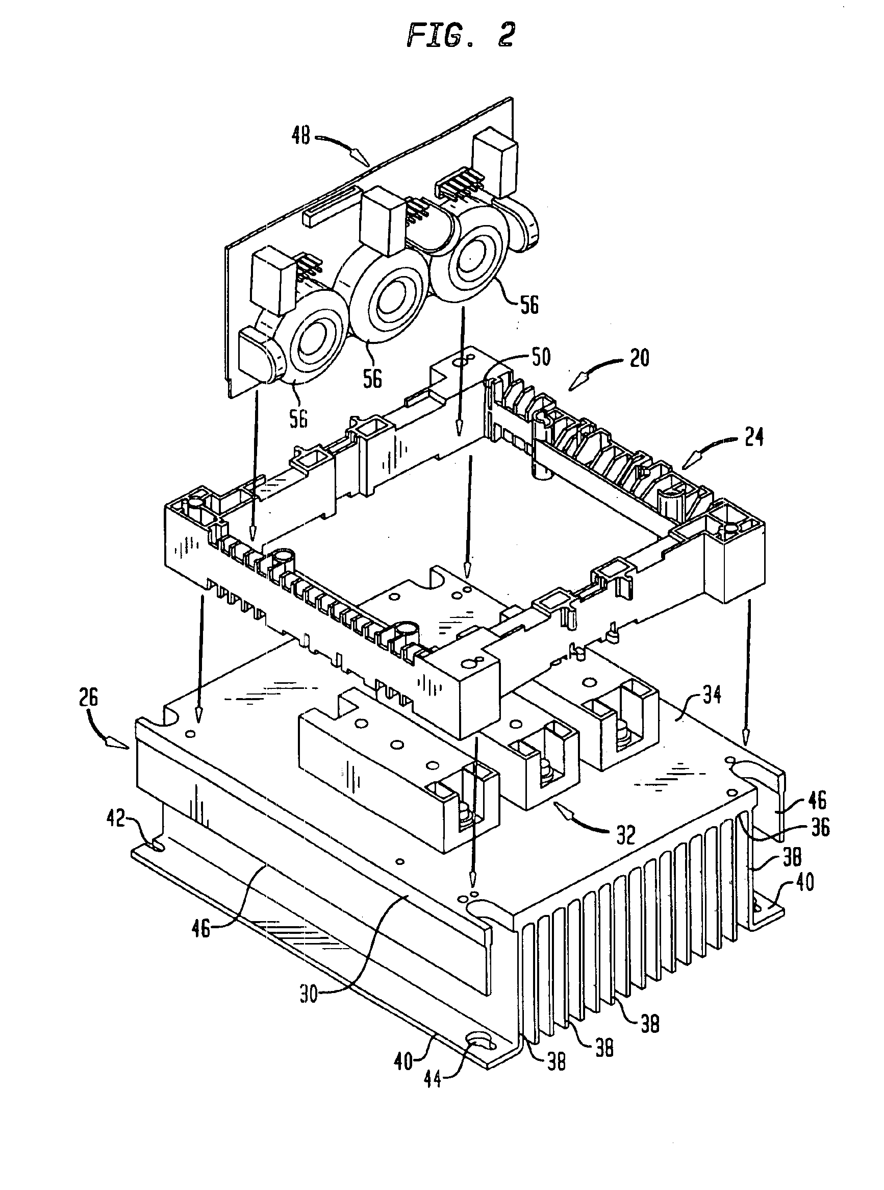
[0029]Referring initially to FIG. 1, a motor controller 20 in the form of a solid state starter / controller 20 is illustrated. Particularly, design of the motor controller 20 in accordance with the invention reduces manufacturing costs and inventory requirements. One application for the controller 20 is as an elevator starter. The motor controller 20 may be used to drive a pump for an hydraulic elevator. Each time movement of an elevator car is commanded, then the motor controller 20 must start the elevator motor until it reaches operating speed and then operate in a run mode. Such a motor controller 20 may only be used for the up direction as gravity may be used for the down direction.

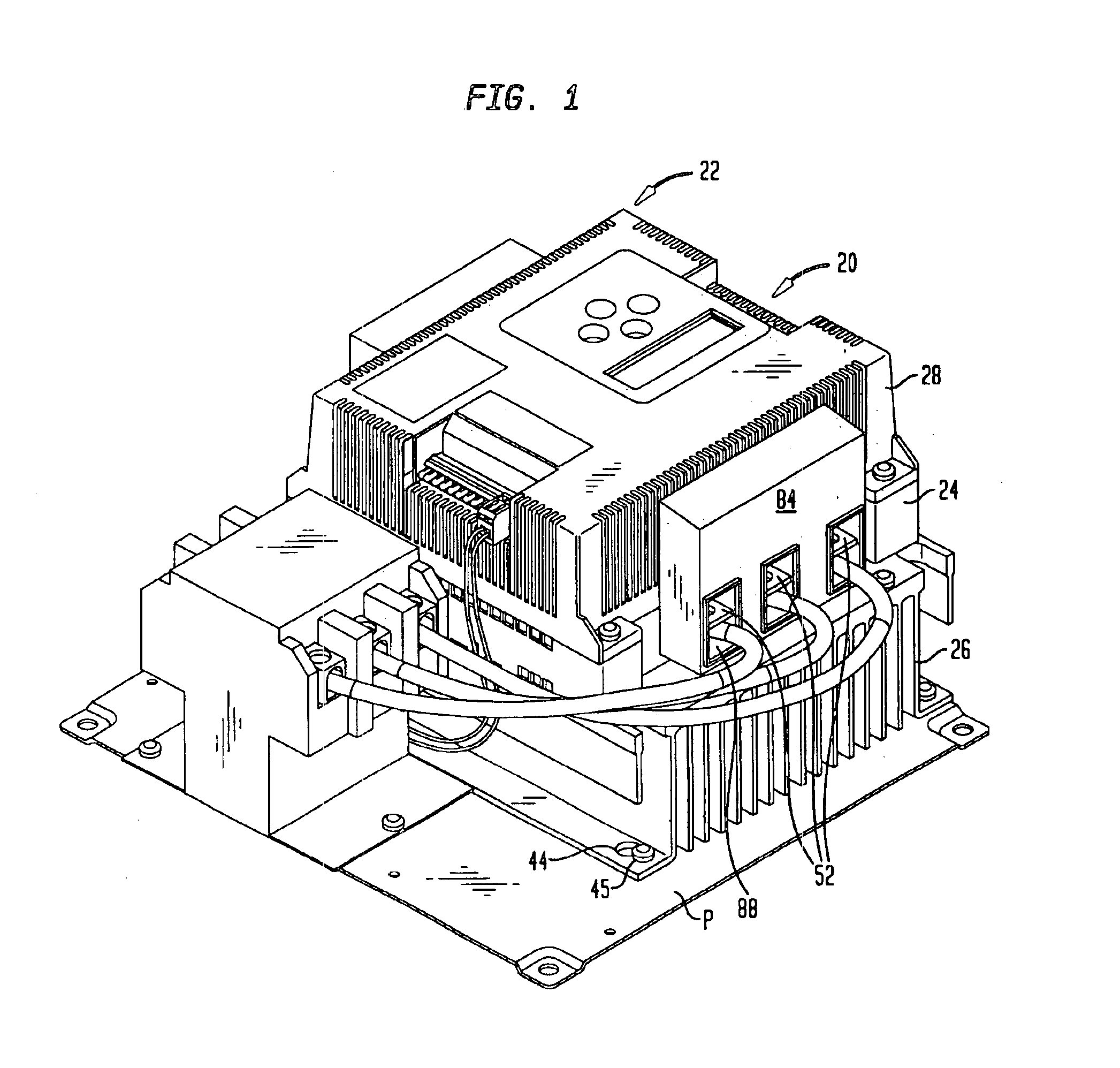
[0030]The motor controller 20 comprises a housing 22 including a housing base 24, a heat sink 26 and a cover 28. Referring also to FIG. 2, the heat sink 26 comprises a planar plate 30. The motor controller 20 includes a plurality of solid state switches 32 in the form of thyristors, such as back to bac...


PUM


Abstract

A modular motor controller family comprises a housing. Solid state switches are selected from one of plural switch sizes for controlling a desired voltage and current range. The switches are mounted in the housing for connection between an AC line and motor terminals for controlling application of AC power to the motor. A logic circuit board is mounted in the housing including logic circuitry for commanding operation of the solid state switches independent of the selected switch size. An interface circuit board selected from one of plural configurations is mounted in the housing and includes interface circuitry connected between the logic circuitry and the solid state switches. The interface circuitry is selected to interface with the selected switch size according to the desired voltage and current range.

Description


Claims


Application Information

Patent Timeline
Owner SIEMENS ENERGY & AUTOMATION INC
Why Eureka
Try Eureka