
Apparatus and method for scaling a switching fabric in a network switching node

a network switching and fabric technology, applied in data switching networks, digital transmission, network connections, etc., can solve the problems of high implementation cost and complex hardware of switch planes, and achieve the effect of reducing the number of switch planes

Inactive Publication Date: 2005-05-10
PLURIS
View PDF11 Cites 27 Cited by
  • Summary
  • Abstract
  • Description
  • Claims
  • Application Information

AI Technical Summary

Benefits of technology

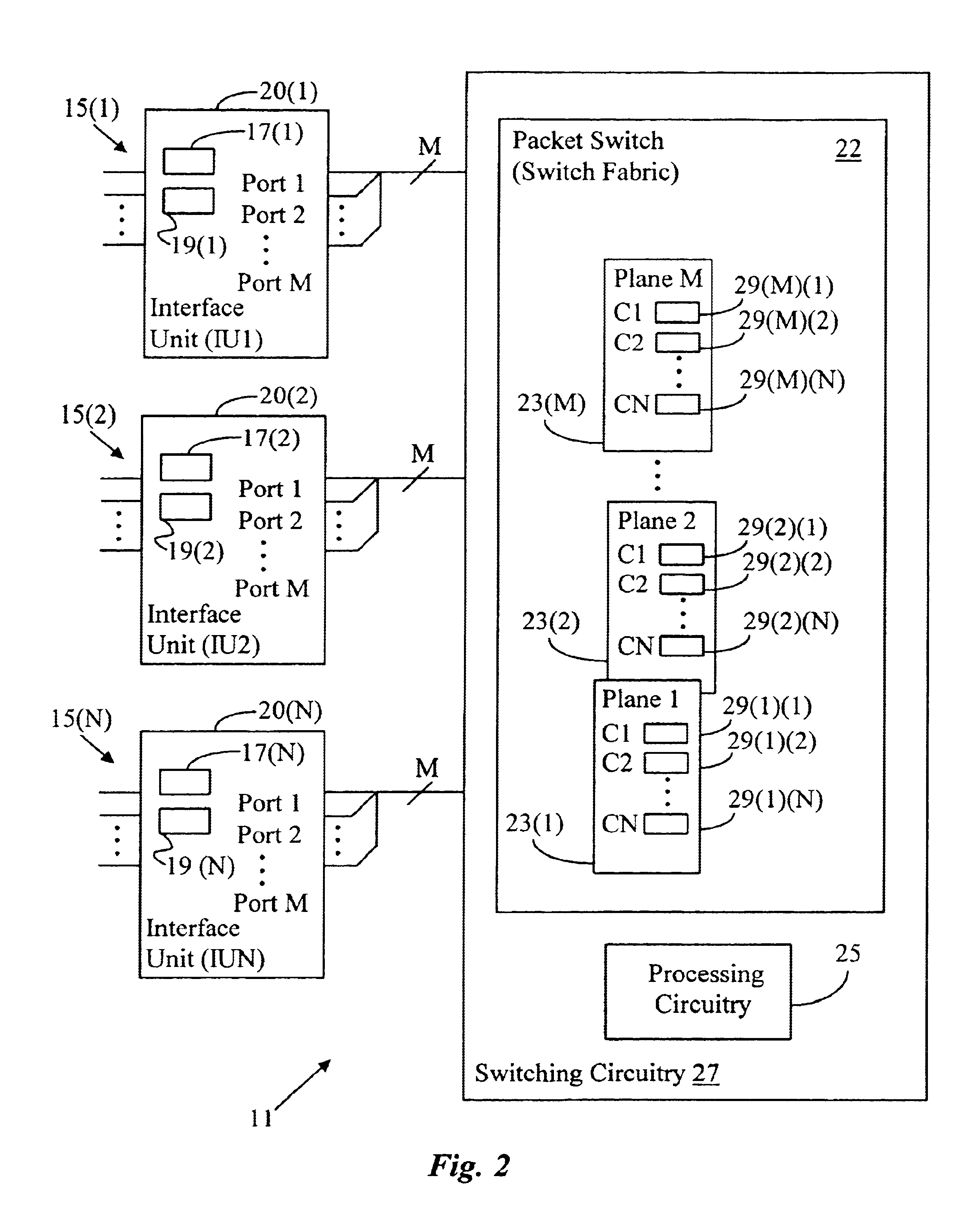
[0003]The present invention provides a method and apparatus which reduces the number of switch planes required to implement a switch fabric by altering how the switch planes and data ports are allocated. The system of the invention is applicable in a system such as a network switching node in which data are transferred among a plurality of interface units, each having a plurality of data ports, connected across a switching fabric of node switching circuitry. The fabric is partitionable into a plurality of switch planes such that each switch plane is assignable to transfer data associated with a like data port of the plurality of interface units. Each switch plane includes multiple switching channels each assignable to transfer data associated with one data port on one of the interface units. In accordance with the invention, a number of interface units connected to the switch fabric is determined. If the number of interface units is less than the number of switching channels in each switch plane, then, for at least one of the switch planes, a first channel of the switch plane is assigned to transfer data associated with a first data port of a first interface unit and a second channel in the at least one switch plane is assigned to transfer data associated with a second port of the first interface unit.
[0007]The reallocation method and apparatus of the invention provide a scalable switching fabric. The scaling can be performed as described above to reduce the size and hardware complexity and, therefore, the cost of the switching fabric in cases where fewer interface units are used than would be used in a full implementation. Likewise, the reallocation can be reversed such that the switching fabric can be scaled back to a larger size in the event that it is desired to add interface units to the fabric. Therefore, the reallocation of the invention provides for a flexible scalable switching fabric which can be sized up and down depending upon changing system requirements.
[0011]Hence, the switch reallocation apparatus and method of the invention provides a means for substantially reducing the amount of hardware required to implement a switch fabric in a switching node in which the full data switching capability of the node is not implemented, either on a temporary or permanent basis. By reallocating the port connections to the switch fabric, the number of switch planes that must be implemented can be substantially reduced, leading to reduced hardware complexity and cost. The invention also provides the capability of scaling or “unfolding” the switch fabric back up to a larger implementation to accommodate expansion of the system by addition of new interface units.

Problems solved by technology

Consequently, switch planes can be extremely complex pieces hardware which can be very expensive to implement.

Method used


Image

  • Apparatus and method for scaling a switching fabric in a network switching node
  • Apparatus and method for scaling a switching fabric in a network switching node
  • Apparatus and method for scaling a switching fabric in a network switching node

Examples


Embodiment Construction

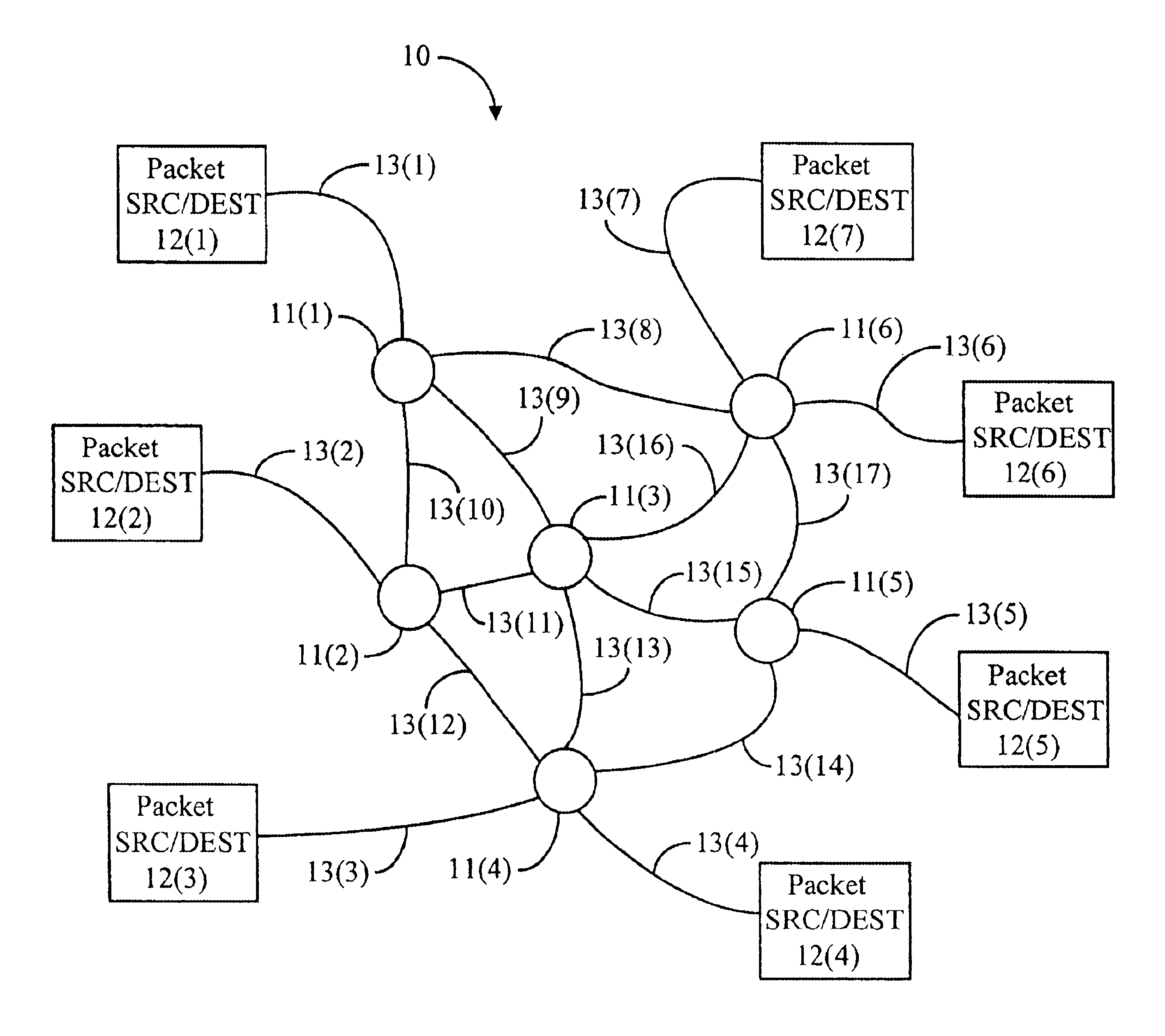
[0028]FIG. 1 schematically depicts a computer network 10 in which the invention can be applied. The network 10 includes a plurality of switching nodes 11(1) through 11 (N), generally identified by reference numeral 11, for transferring signals representing data among a number of devices, which in FIG. 1 are represented by packet source / destination devices 12(1) through 12(M), generally identified by reference numeral 12, in a wide area network (“WAN”). The packet source / destination devices 12 can include a particular device such as a computer system or other device that stores, generates, processes or otherwise uses digital data. It can also be a local area network of such devices. Each packet source / destination device 12 is connected over a communication link, generally identified by reference numeral 13, to a switching node 11 to facilitate transmission of data thereto or the reception of data therefrom.

[0029]The switching nodes 11 are interconnected by communication links, also g...


PUM


Abstract

A method and apparatus for reallocating switching circuitry in a switching fabric are disclosed. The switching fabric is used to permit data transfer among a plurality of interface units each having a plurality of data ports. The switching fabric is partitionable into a plurality of switch planes such that each switch plane can be assigned to transfer data associated with like data ports of the interface units. Each switch plane includes multiple switching channels each assignable to transfer data associated with one data port of one of the interface units, in a full implementation. The number of interface units is less than the number of switching channels in a switch plane, then the reallocation is performed such that multiple channels of at least one switch plane can be assigned to transfer data of multiple ports of at least one of the interface units. This results in switch plane channels that would otherwise be unused being utilized to transfer data. This reallocation of switch plane channels can result in the elimination of one or more switch planes from the switch fabric resulting in substantially reduced hardware complexity and cost.

Description

BACKGROUND OF THE INVENTION[0001]In many complex systems such as digital communications systems, switching systems or “switching fabrics” are employed to route data between system modules. For example, in a network node on a digital network, a switching fabric can be used to route data packets between ports on the node, each of which, in a general bidirectional system, can serve as both an input port and an output port. The switching nature of the fabric refers to its ability to controllably route individual data packets from one of many data ports to another of the data ports.[0002]Some switching fabrics are implemented as multiple switch “planes” or “slices”, each of which handles a portion of the total switching capability of the fabric. The switch planes are allocated in a configuration which in general permits each port to transfer data to all of the ports, including through the switching fabric back to itself. Consequently, switch planes can be extremely complex pieces hardwar...

Claims


Application Information

Patent Timeline
IPC IPC(8): H04L12/56
CPCH04L49/1523H04L49/25
Inventor SCHWARTZ, STEVEN J.SPADA, ERIC J.PELLETIER, ERIC J.KOEHLER, JEFFREY A.
Owner PLURIS
Learn More