Electro-mechanical roll product dispenser

a technology of electronic mechanical and product dispensers, applied in the field of dispensers, can solve the problems of inordinate resistance of dispensers, high manufacturing and maintenance costs, and complicated conventional mechanical sanitary dispensers utilizing automatic mechanical cutting and feeding mechanisms

Inactive Publication Date: 2005-05-17
KIMBERLY-CLARK WORLDWIDE INC
View PDF27 Cites 96 Cited by
  • Summary
  • Abstract
  • Description
  • Claims
  • Application Information

AI Technical Summary

Benefits of technology

[0014]Any number of devices may be utilized to brake the feed roller. In one embodiment, an electric brake may be configured with the motor. The brake is energized to stop the motor shaft from rotating upon receipt of a “brake-on” trigger signal from the revolution counter and control circuit. In one embodiment, the electric brake may comprise a relatively simple solenoid that, when activated, engages a plunger into a recess or hole in the

Problems solved by technology

Although effective, the conventional mechanical sanitary dispensers utilizing automatic mechanical cutting and feeding mechanisms can be relatively complicated from a mechanical component standpoint and expensive to manufacture and maintain.
Also, some users have noted that such dispensers present an inordinate amount of resista

Method used


Image

  • Electro-mechanical roll product dispenser
  • Electro-mechanical roll product dispenser
  • Electro-mechanical roll product dispenser

Examples


Embodiment Construction

[0023]Reference will now be made in detail to embodiments of the present invention, at least one example of which is illustrated in the Figs. Each embodiment is provided by way of explanation of the invention, at not meant as a limitation of the invention. For example, features illustrated or described as part of one embodiment may be used with another embodiment to yield still a further embodiment. It is intended that the present invention include these and other modifications and variations as come within the scope and spirit of the invention.

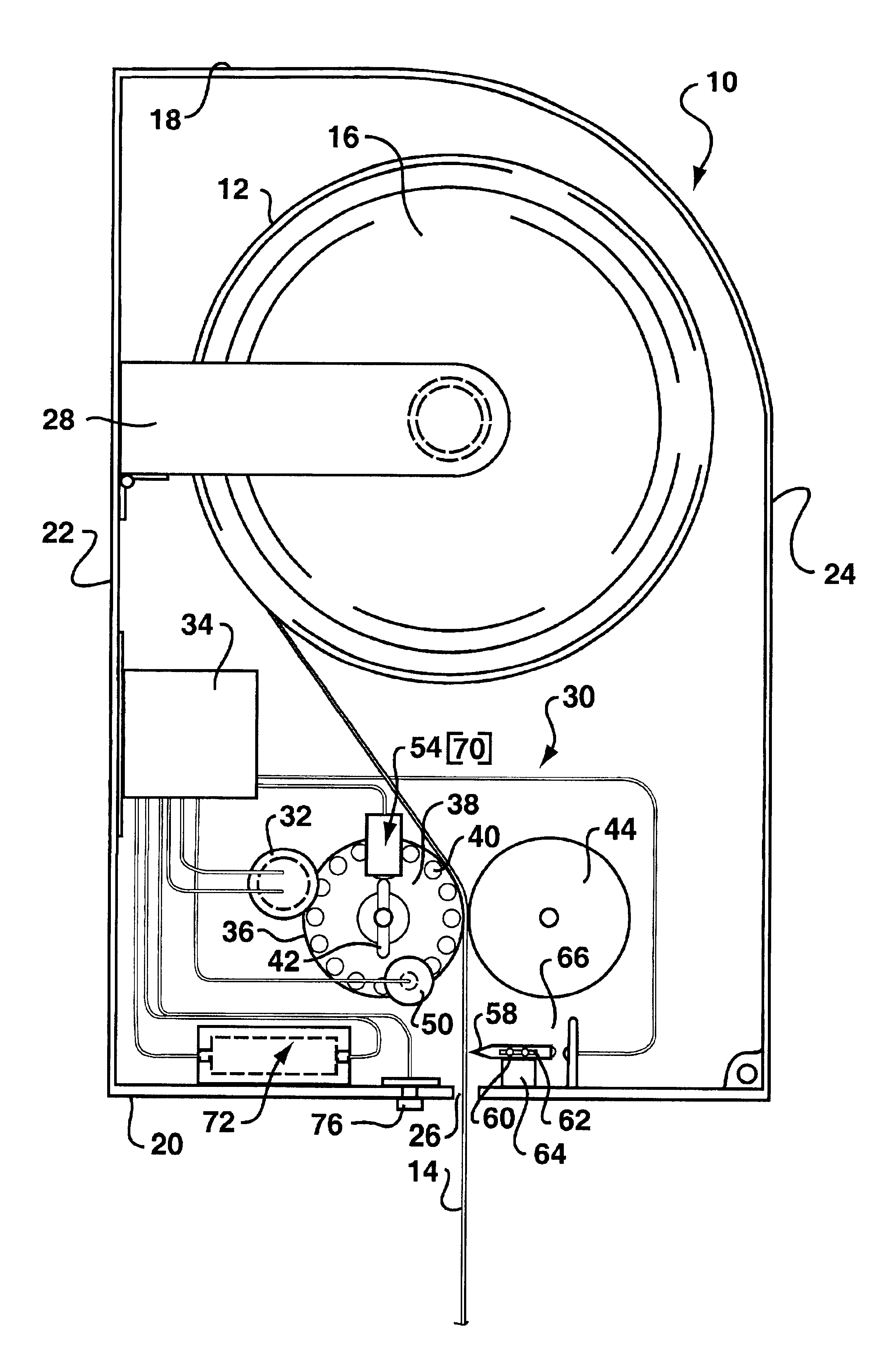
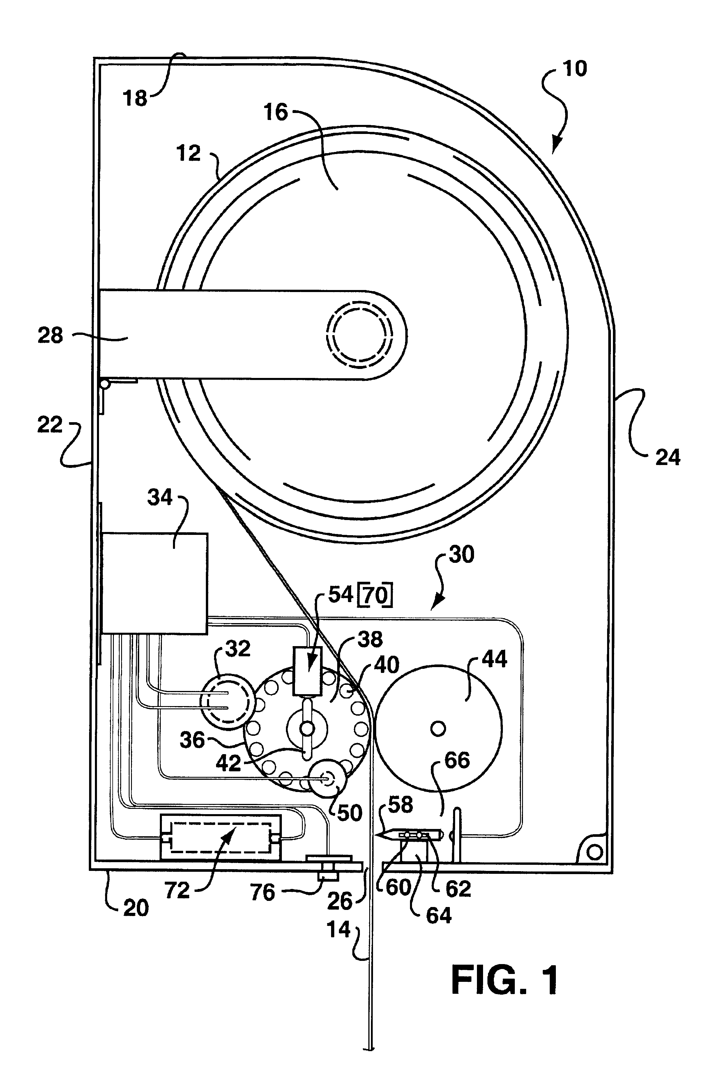
[0024]An embodiment incorporating basic operational features of a dispenser according to the present invention is indicated as a dispenser 10 in the figures. The dispenser 10 is configured to dispense a primary roll 12 of towel material 16 that may comprise, for example, a standard eight-inch towel roll. The dispenser 10 includes a housing 18 of any general shape and configuration. The housing 18 includes a bottom portion 20, a front portion ...


PUM

PropertyMeasurementUnit
Lengthaaaaaaaaaa
Poweraaaaaaaaaa

Abstract

An electro-mechanical roll towel dispenser includes a housing with a roll carrier disposed therein to rotationally support a roll of towel material. An electro-mechanical feed mechanism is disposed in the housing to dispense measured sheets of the towel material. The feed mechanism operates in a first mechanical operational mode wherein the towel sheets are dispensed by a user grasping and pulling on a tail of the towel material extending from the housing, and a second electrical operational mode wherein a measured length of a next sheet is automatically and electrically fed out of the housing to define the tail for the next user.

Description

BACKGROUND OF THE INVENTION[0001]The present invention relates to a dispenser for a roll of web material, and particularly to a sanitary dispenser that dispenses a measured amount of material upon a user grasping and pulling the “tail” end of the roll material.[0002]A number of dispensing devices are well known in the art for dispensing and cutting webs or roll material such as paper toweling. With such dispensers, the process of dispensing and cutting the web material is carried out automatically by a user pulling on the free “tail” end of the web material that extends from a dispensing slot in the apparatus. In a typical configuration, the web material is engaged against a rough friction enhancing surface of a feed drum and the action of pulling the web tail causes the drum to rotate. The drum includes a drive mechanism and, after the initial pull on the web tail by a user, the drum is driven a predetermined rotational degree to dispense a metered amount of the material. A cam dri...

Claims


Application Information

Patent Timeline
IPC IPC(8): A47K10/36A47K10/24
CPCA47K10/36A47K10/3612A47K10/3625Y10T83/4455Y10T83/6668Y10T83/896Y10T225/209Y10T225/252Y10T225/287
Inventor KAPILOFF, DAVID
Owner KIMBERLY-CLARK WORLDWIDE INC
Why Eureka
Try Eureka