Granular matter filled weapon guidance electronics unit

a technology of electronics unit and granular matter, which is applied in the direction of electric fuzes, electric apparatus casings/cabinets/drawers, ammunition fuzes, etc., can solve the problems of not having a prior art that protects rigidly mounted guidance electronics units from the shock of explosive launch

Inactive Publication Date: 2005-05-17
RAYTHEON CO
View PDF18 Cites 24 Cited by
  • Summary
  • Abstract
  • Description
  • Claims
  • Application Information

AI Technical Summary

Benefits of technology

[0008]In accordance with the present invention, granular material is used to essentially completely fill the void in the guidance housing and surround the circuit card assemblies so that there is little chance that anything can move. Such granular material, which is similar to the consistency of fine beach sand, does not compress during the shock of gun launch; consequently, no damage to any of the circuit cards or components on the cards occurs. The granular material surrounds the circuit cards so that any loads on the guidance electronics unit are distributed much more equally throughout the circuit cards. The granular material also holds large components in place so that they survive any shock or vibration loads that are often made worse due to their mass.
[0012]substantially filling all spaces surrounding each circuit card assembly with a granular material to provide support for each circuit card assembly during explosive launch.
[0013]The present invention solves the problem of making it possible for guidance electronics to survive the large loads encountered during an explosive launch out of a gun or howitzer. The teachings of the present invention may also be used in a guided missile electronics unit using a hollow glass sphere fill material, so that the weight of the fill material is not an issue.
[0014]No known Weapons Guidance Electronics Unit uses granular matter as the structural support of the circuit cards. The present invention could dramatically decrease cost, while increasing simplicity, reworkability, and survivability of numerous weapons.

Problems solved by technology

These metal housings are very expensive to produce and take a long time to design and develop.
However, it appears that there is little prior art that deals with protecting rigidly-mounted guidance electronics units against the shock of explosive launch.

Method used


Image

  • Granular matter filled weapon guidance electronics unit
  • Granular matter filled weapon guidance electronics unit
  • Granular matter filled weapon guidance electronics unit

Examples


Embodiment Construction

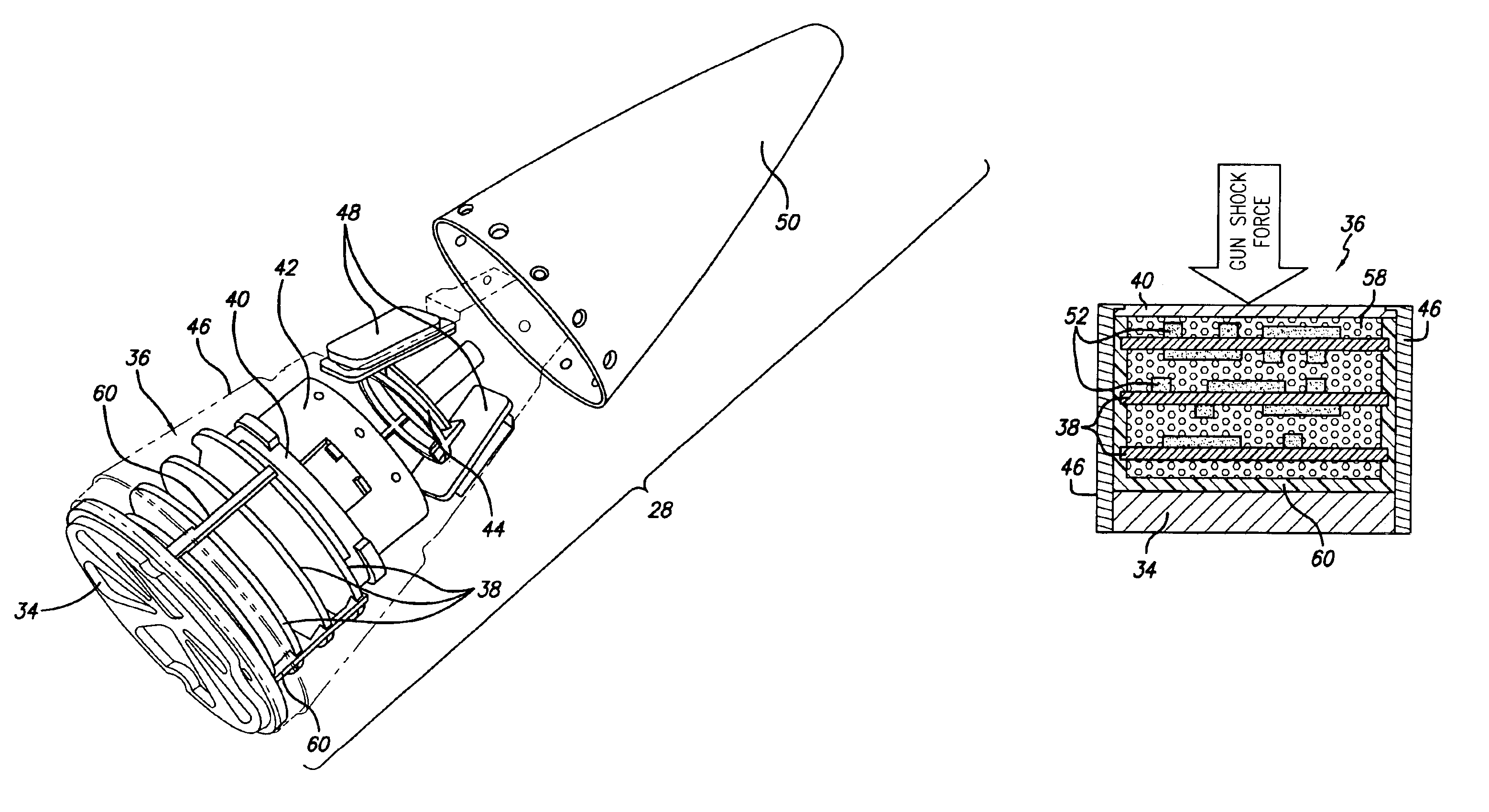
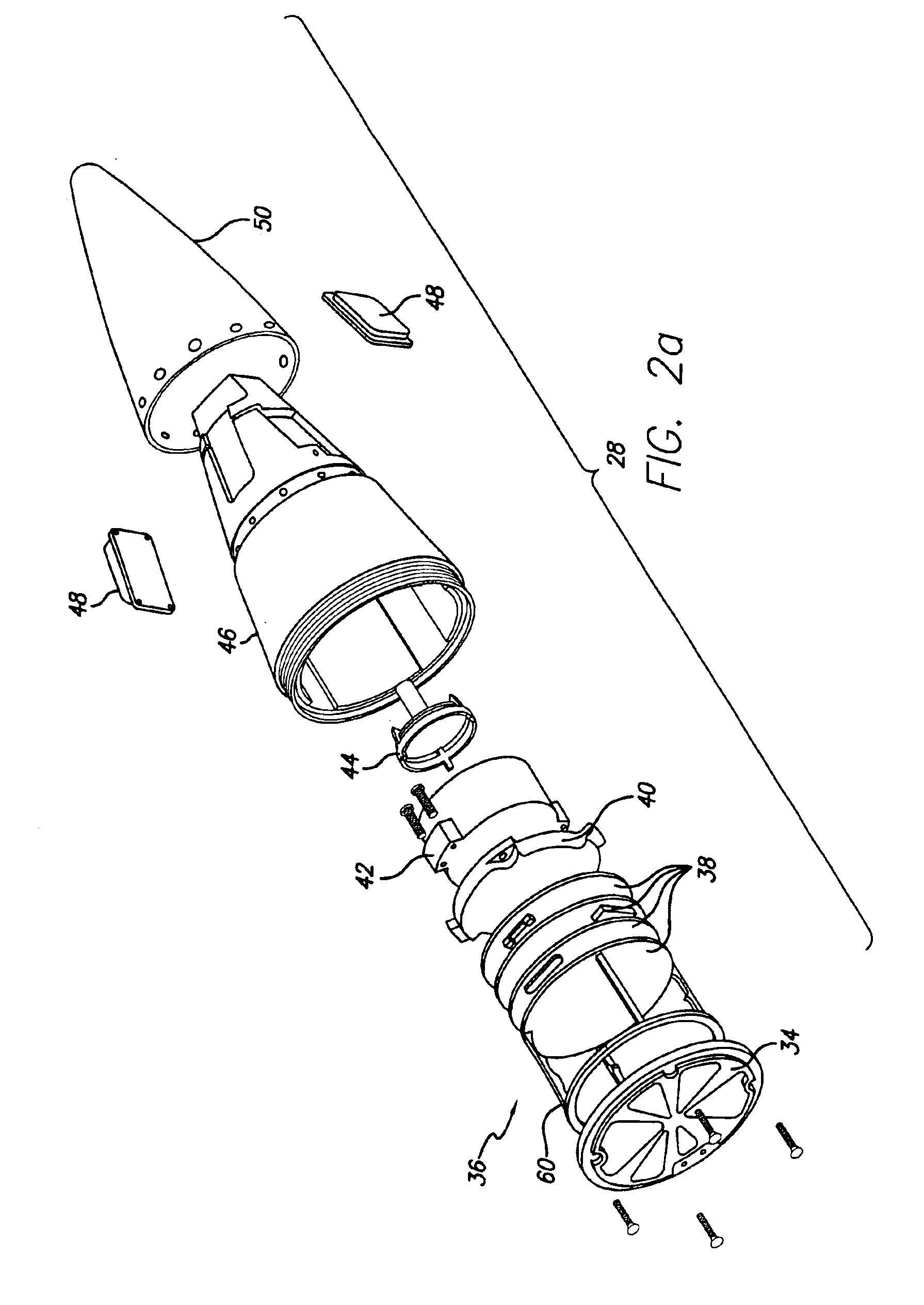
[0019]Nearly all weapons undergo significant mechanical shock and vibration loads due to harsh environments to which they are exposed. These environments can include such things as transportation, launch, and captive carry on an aircraft. These loads cause the guidance electronic unit (GEU) to use a structural cage, usually made out of metal, to constrain the GEU circuit card assemblies (CCAs) to ensure that the sensitive electronic components on the GEU CCAs and the electrical interconnections remain functional.

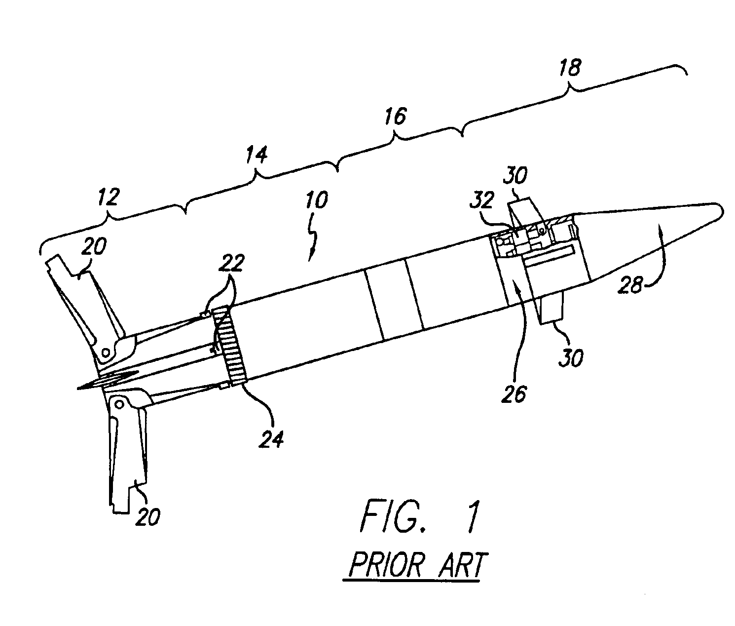
[0020]FIG. 1 depicts a common projectile 10, such as a cannon-launched guided projectile. The projectile 10 comprises a base section 12 at its aft end, and proceeding from the aft end to the forward end a propulsion section 14, a payload section 16, and a guidance section 18.

[0021]The base section 12 includes a plurality of stabilizing fins 20, which in the firing position are held flush with the outer surface of the base section 12 by latching mechanism 22. When the project...


PUM


Abstract

A guidance electronics unit is provided for an explosively-launched vehicle, e.g., a projectile or missile, comprising a plurality of circuit card assemblies, each circuit card assembly containing a plurality of electronic components and interconnections, each circuit card assembly maintained in a housing and spaced apart. All spaces surrounding each circuit card assembly are filled with a granular material to provide support for each circuit card assembly during explosive launch. Further, a method for supporting circuit card assemblies in the guidance electronics unit is provided. The problem of enabling guidance electronics to survive the large loads encountered during an explosive launch out of a gun, such as a howitzer, or missile launch tube is thereby solved.

Description

TECHNICAL FIELD[0001]The present invention is directed to guidance electronics units, and, more particularly, to stabilizing circuit cards in such units so as to avoid damage during the shock of gun launch.BACKGROUND ART[0002]Guided weapon design necessitates the need for a guidance electronics unit (GEU), which is the brain of the system. The GEU includes functions such as the mission computer, guidance, navigation, and control of the weapon, along with other weapon specific functions. The GEU consists of multiple circuit card assemblies (CCAs) that are usually arranged in close proximity to each other.[0003]Guidance electronics units (GEUs) are used in a variety of weapons that are subject to sudden forces during an explosive launch, such as firing the weapon from a gun or howitzer or launching a missile.[0004]Typical designs for a guidance electronics unit consists of circuit card assemblies held together by metal housings, often with very precise machining. These metal housings ...

Claims


Application Information

Patent Timeline
Patent Type & Authority Patents(United States)
IPC IPC(8): F42C11/00F41G7/20F41G7/22H05K3/28H05K1/14H05K1/02F42B15/08F42C19/06
CPCF41G7/22F42B15/08F42C11/002H05K3/284F42C19/06H05K1/0271H05K1/144
Inventor ZIMMERMAN, CRAIG A.DYSTER, JUSTIN C.BOSSE, MATHEW H.LANGE, NORMANADAMS, TOVANRODRIGUEZ, LEE
Owner RAYTHEON CO
Why Eureka
Try Eureka